|
07.04.2008
Updated 23.04.2008
Vyatta VC4 - Advanced VPN Site-to-Site Connections - Part 6 - Configure the GRE and IPIP Tunnels in Case of Scenario 1
- 1. Vyatta HQ GRE Tunnels Config
- 2. Vyatta Branch1 GRE Tunnel Config
- 3. Vyatta Branch2 GRE Tunnel Config
- 4. GRE - Make The hub-and-spoke Topology a Mesh One
- 5. Vyatta HQ IPIP Tunnels Config
- 6. Vyatta Branch1 IPIP Tunnel Config
- 7. Vyatta Branch2 IPIP Tunnel Config
- 8. IPIP - Make The hub-and-spoke Topology a Mesh One
Now that we've entered a basic configuration on Vyatta VC4 VMs and made sure that we do not have connectivity problems, we can proceed and test the GRE and IPIP tunnels in case of Scenario 1. If you do not recall what was Scenario 1 take a look here.
First we will configure them without IPsec protection to see how they behave. Since we are in our private lab, security is not a problem. I suppose I do not have to remind you that, in practice, if you simply first configure the GRE or IPIP tunnels without IPsec protection to make sure that they are up and working, *anybody* with access to the wire can hack into your network (the portion of it accessible through the tunnels).
Actually I want to point out an aspect: Vyatta really shines in a particular area: if you have to do a deployment in practice, you can actually do so having a working and tested configuration. First you can easily do the tests using a VMware lab for example, find a working configuration and optimize this configuration. Then, with the confidence gained over your configuration files, deployment should be easy and trouble free.
And the branch office admins can be provided with a fully workable configuration file to enter on their Vyatta machines.
These aspects are quite important because they can save time and money.
As in Part 5, I will enable VMware Network AdapterVMnet5, see Figure71.
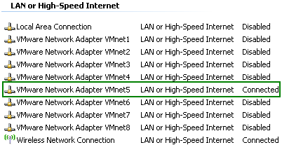
Figure71: VMware Network Adapter VMnet5 Enabled
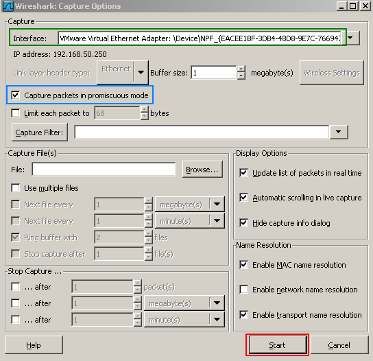
And before entering the configuration lines on the Vyatta VC4 machines, I will start a Wireshark capture on the VMnet5 interface on the host machine(see Figure72, make sure "Capture packets in promiscous mode " is selected) . Doing so, I will have central point of view over the traffic sent between Vyatta VC4 machines, I will see the first packets sent through the tunnels, the OSPF multicast packets and so on. This is very useful for troubleshooting and we can actually see how things work.
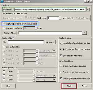
Figure72: Start a Wireshark capture on the VMnet5 interface on the host machine
1. Vyatta HQ GRE Tunnels Config
On the Vyatta HQ machine, since we are using a hub-and-spoke topology and Vyatta HQ is the hub, we will create two GRE point-to-point tunnels, one to Branch1 and the other to Branch2. In practice you may shrink the IP address ranges from the tunnel interfaces from /24 to /30(since these are point-to-point tunnels).
set interfaces tunnel tun1
set interfaces tunnel tun1 address 192.168.111.1/24
set interfaces tunnel tun1 description "Gre Tunnel to Branch1"
set interfaces tunnel tun1 encapsulation gre
set interfaces tunnel tun1 local-ip 192.168.50.2
set interfaces tunnel tun1 remote-ip 192.168.50.3 7
set interfaces tunnel tun2
set interfaces tunnel tun2 address 192.168.121.1/24
set interfaces tunnel tun2 description "Gre Tunnel to Branch2"
set interfaces tunnel tun2 encapsulation gre
set interfaces tunnel tun2 local-ip 192.168.50.2
set interfaces tunnel tun2 remote-ip 192.168.50.4
commit
And we will run OSPF through these tunnels to discover the networks behind the other Vyatta VC4 machines.
set protocols ospf area 100
set protocols ospf area 100 network 192.168.10.0/24
set protocols ospf area 100 network 192.168.111.0/24
set protocols ospf area 100 network 192.168.121.0/24
set protocols ospf log-adjacency-changes
commit
2. Vyatta Branch1 GRE Tunnel Config
On the Vyatta Branch1 machine, which will be a spoke, we will create one GRE point-to-point tunnel, to Vyatta HQ.
set interfaces tunnel tun1
set interfaces tunnel tun1 address 192.168.111.2/24
set interfaces tunnel tun1 description "Gre Tunnel to HQ"
set interfaces tunnel tun1 encapsulation gre
set interfaces tunnel tun1 local-ip 192.168.50.3
set interfaces tunnel tun1 remote-ip 192.168.50.2
commit
And we will run OSPF through this tunnel to discover the networks behind the other Vyatta VC4 machines.
set protocols ospf area 100
set protocols ospf area 100 network 192.168.30.0/24
set protocols ospf area 100 network 192.168.111.0/24
set protocols ospf log-adjacency-changes
commit
3. Vyatta Branch2 GRE Tunnel Config
On the Vyatta Branch2 machine, which will be a spoke, we will create one GRE point-to-point tunnel, to Vyatta HQ.
set interfaces tunnel tun1
set interfaces tunnel tun1 address 192.168.121.2/24
set interfaces tunnel tun1 description "Gre Tunnel to HQ"
set interfaces tunnel tun1 encapsulation gre
set interfaces tunnel tun1 local-ip 192.168.50.4
set interfaces tunnel tun1 remote-ip 192.168.50.2
commit
And we will run OSPF through this tunnel to discover the networks behind the other Vyatta VC4 machines.
set protocols ospf area 100
set protocols ospf area 100 network 192.168.40.0/24
set protocols ospf area 100 network 192.168.121.0/24
set protocols ospf log-adjacency-changes
commit
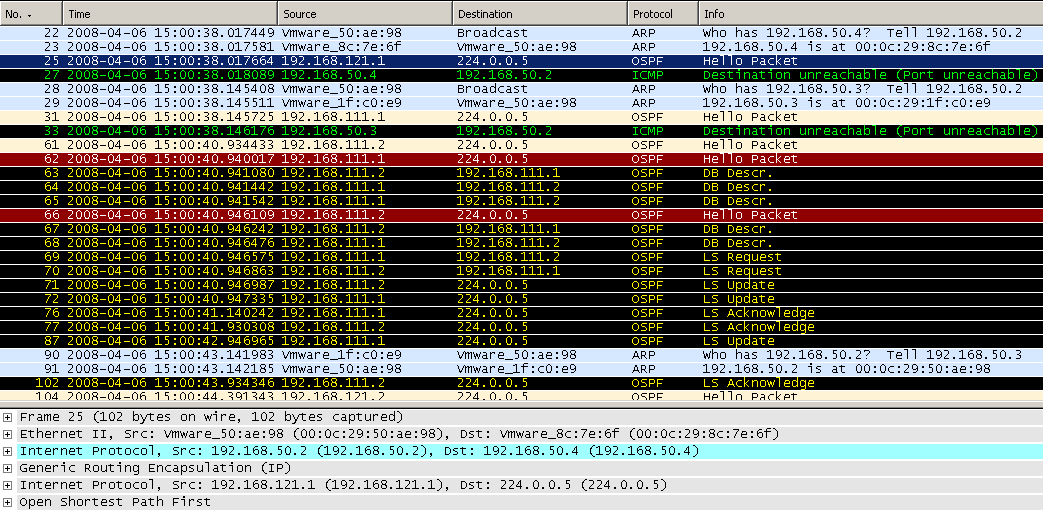
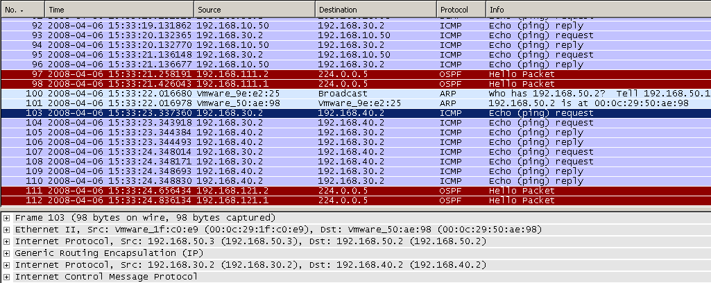
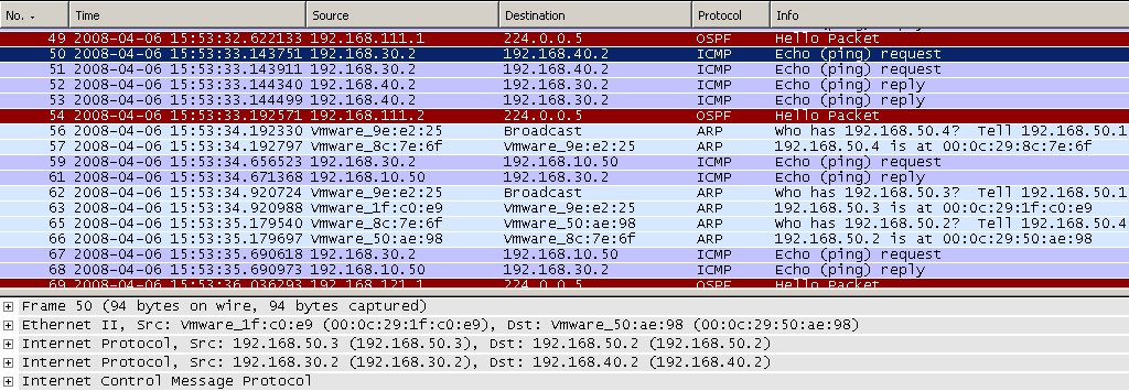
If we take a look at the Wireshark capture, we will notice that it recorded some activity, a sign that our tunnels are working. In Figure73 we can spot OSPF traffic sent through the GRE tunnel between HQ and Branch1.
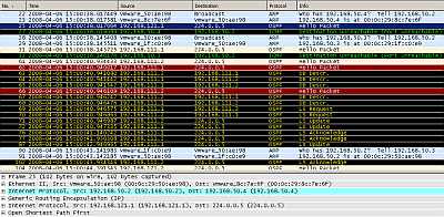
Figure73: Wireshark Capture GRE Tunnels: OSPF Traffic
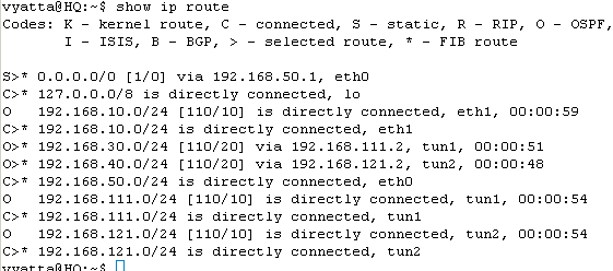
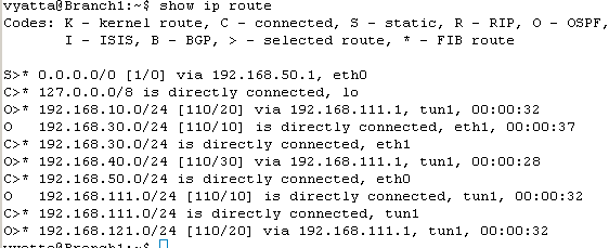
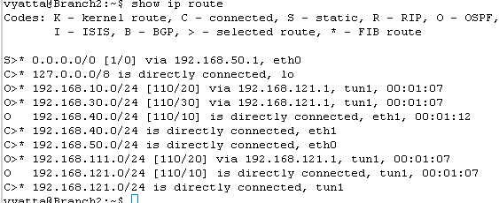
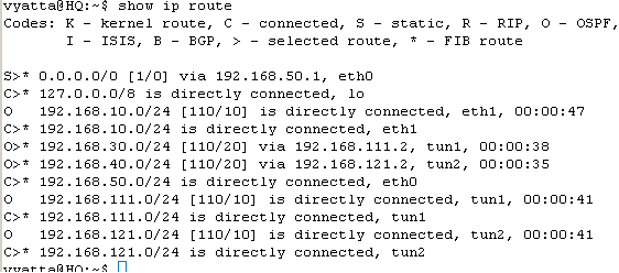
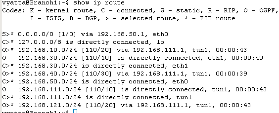
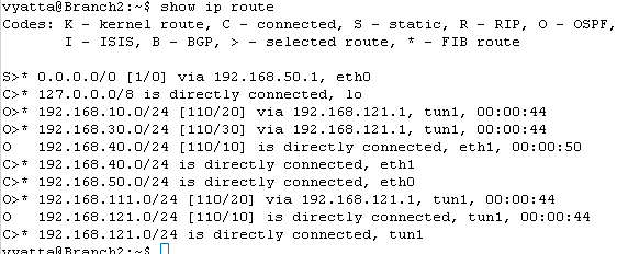
Let's check the routing table on the Vyatta HQ, Vyatta Branch1 and Vyatta Branch2, see Figure74, Figure75 and Figure76 . We can notice that every Vyatta VC4 machine is now aware of the networks behind the other Vyatta VC4 machines.
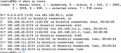
Figure74: Vyatta HQ GRE Tunnels: Routing Table
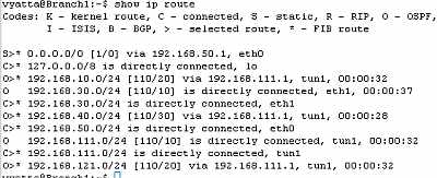
Figure75: Vyatta Branch1 GRE Tunnels: Routing Table
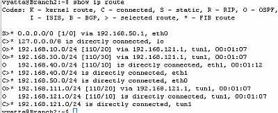
Figure76: Vyatta Branch2 GRE Tunnels: Routing Table
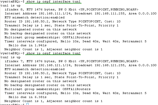
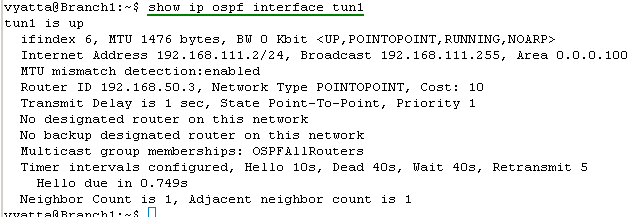
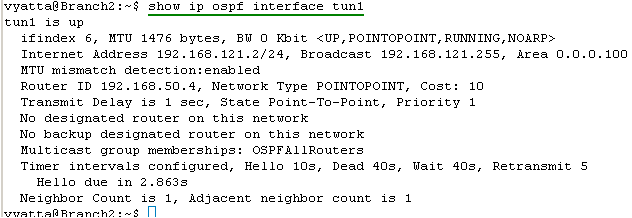
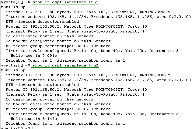
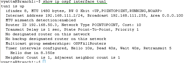
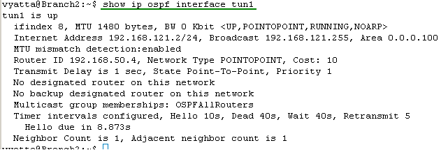
Let's look at the OSPF information about the tunnel interfaces on the Vyatta HQ, Vyatta Branch1 and Vyatta Branch2 (note the MTU too), see Figure77, Figure78 and Figure79.
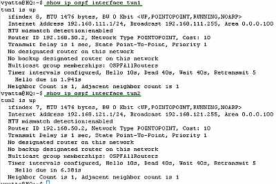
Figure77: Vyatta HQ GRE Tunnels: show ip ospf interface tun1 and tun2
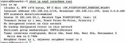
Figure78: Vyatta Branch1 GRE Tunnels: show ip ospf interface tun1
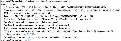
Figure79: Vyatta Branch2 GRE Tunnels: show ip ospf interface tun1
Let's see if we have connectivity between hosts located behind Vyatta VC4 machines, see Figure80, Figure81 and Figure82.
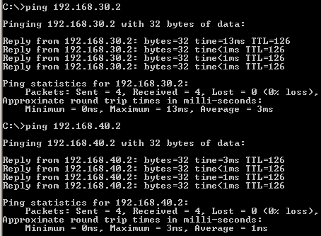
Figure80: GRE Tunnels: Ping from a Host Behind Vyatta HQ to Hosts Behind Vyatta Branch1 and Vyatta Branch2
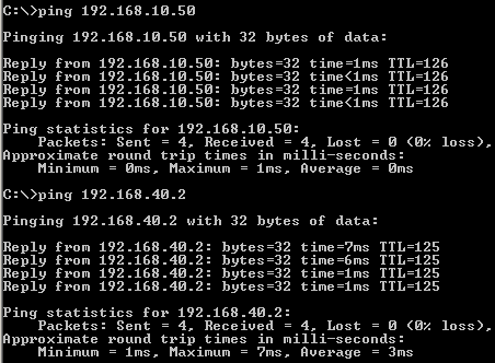
Figure81: GRE Tunnels: Ping from a Host Behind Vyatta Branch1 to Hosts Behind Vyatta HQ and Vyatta Branch2
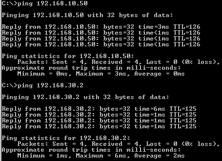
Figure82: GRE Tunnels: Ping from a Host Behind Vyatta Branch2 to Hosts Behind Vyatta HQ and Vyatta Branch1
The ping traffic we generated was recorded by our Wireshark capture, see Figure83.
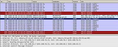
Figure83: Wireshark Capture GRE Tunnels: Ping
Things look good.
All the configuration lines entered on Vyatta HQ, Vyatta Branch1 and Vyatta Branch2 can be found here:
- Vyatta HQ
- Vyatta Branch1
- Vyatta Branch2
4. GRE - Make The hub-and-spoke Topology a Mesh One
If you want, you can make the hub-and-spoke topology a mesh one, by configuring a point-to-point GRE tunnel between Branch1 and Branch2.
On Branch1 add:
set interfaces tunnel tun2
set interfaces tunnel tun2 address 192.168.131.1/24
set interfaces tunnel tun2 description "Gre Tunnel to Branch2"
set interfaces tunnel tun2 encapsulation gre
set interfaces tunnel tun2 local-ip 192.168.50.3
set interfaces tunnel tun2 remote-ip 192.168.50.4
set protocols ospf area 100 network 192.168.131.0/24
On Branch2 add:
set interfaces tunnel tun2
set interfaces tunnel tun2 address 192.168.131.2/24
set interfaces tunnel tun2 description "Gre Tunnel to Branch1"
set interfaces tunnel tun2 encapsulation gre
set interfaces tunnel tun2 local-ip 192.168.50.4
set interfaces tunnel tun2 remote-ip 192.168.50.3
set protocols ospf area 100 network 192.168.131.0/24
5. Vyatta HQ IPIP Tunnels Config
On the Vyatta HQ machine, since we are using a hub-and-spoke topology and Vyatta HQ is the hub, we will create two IPIP tunnels, one to Branch1 and the other to Branch2.
set interfaces tunnel tun1
set interfaces tunnel tun1 address 192.168.111.1/24
set interfaces tunnel tun1 description "IPIP Tunnel to Branch1"
set interfaces tunnel tun1 encapsulation ipip
set interfaces tunnel tun1 local-ip 192.168.50.2
set interfaces tunnel tun1 remote-ip 192.168.50.3
set interfaces tunnel tun2
set interfaces tunnel tun2 address 192.168.121.1/24
set interfaces tunnel tun2 description "IPIP Tunnel to Branch2"
set interfaces tunnel tun2 encapsulation ipip
set interfaces tunnel tun2 local-ip 192.168.50.2
set interfaces tunnel tun2 remote-ip 192.168.50.4
commit
And we will run OSPF through these tunnels to discover the networks behind the other Vyatta VC4 machines.
set protocols ospf area 100
set protocols ospf area 100 network 192.168.10.0/24
set protocols ospf area 100 network 192.168.111.0/24
set protocols ospf area 100 network 192.168.121.0/24
set protocols ospf log-adjacency-changes
commit
6. Vyatta Branch1 IPIP Tunnel Config
On the Vyatta Branch1 machine, which will be a spoke, we will create one IPIP tunnel, to Vyatta HQ.
set interfaces tunnel tun1
set interfaces tunnel tun1 address 192.168.111.2/24
set interfaces tunnel tun1 description "IPIP Tunnel to HQ"
set interfaces tunnel tun1 encapsulation ipip
set interfaces tunnel tun1 local-ip 192.168.50.3
set interfaces tunnel tun1 remote-ip 192.168.50.2
commit
And we will run OSPF through this tunnel to discover the networks behind the other Vyatta VC4 machines.
set protocols ospf area 100
set protocols ospf area 100 network 192.168.30.0/24
set protocols ospf area 100 network 192.168.111.0/24
set protocols ospf log-adjacency-changes
commit
7. Vyatta Branch2 IPIP Tunnel Config
On the Vyatta Branch2 machine, which will be a spoke, we will create one IPIP tunnel, to Vyatta HQ.
set interfaces tunnel tun1
set interfaces tunnel tun1 address 192.168.121.2/24
set interfaces tunnel tun1 description "IPIP Tunnel to HQ"
set interfaces tunnel tun1 encapsulation ipip
set interfaces tunnel tun1 local-ip 192.168.50.4
set interfaces tunnel tun1 remote-ip 192.168.50.2
commit
And we will run OSPF through this tunnel to discover the networks behind the Vyatta VC4 machines.
set protocols ospf area 100
set protocols ospf area 100 network 192.168.40.0/24
set protocols ospf area 100 network 192.168.121.0/24
set protocols ospf log-adjacency-changes
commit
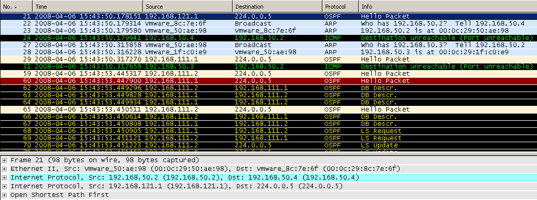
If we take a look at the Wireshark capture, we will notice that it recorded some activity, a sign that our tunnels are working. In Figure84 we can spot OSPF traffic sent through the IPIP tunnel between HQ and Branch1.
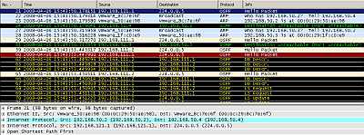
Figure84: Wireshark Capture IPIP Tunnels: OSPF Traffic
Let's check the routing table on the Vyatta HQ, Vyatta Branch1 and Vyatta Branch2, see Figure85, Figure86 and Figure87 . We can notice that every Vyatta VC4 machine is now aware of the networks behind the other Vyatta VC4 machines.

Figure85: Vyatta HQ IPIP Tunnels: Routing Table
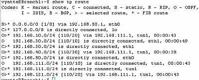
Figure86: Vyatta Branch1 IPIP Tunnels: Routing Table
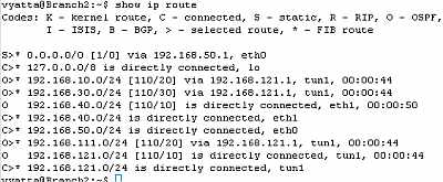
Figure87: Vyatta Branch2 IPIP Tunnels: Routing Table
Let's look at the OSPF information about the tunnel interfaces on the Vyatta HQ, Vyatta Branch1 and Vyatta Branch2 (note the MTU too), see Figure88, Figure89 and Figure90.
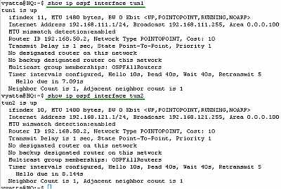
Figure88: Vyatta HQ IPIP Tunnels: show ip ospf interface tun1 and tun2
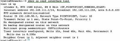
Figure89: Vyatta Branch1 IPIP Tunnels: show ip ospf interface tun1
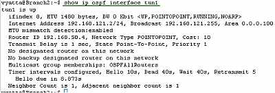
Figure90: Vyatta Branch2 IPIP Tunnels: show ip ospf interface tun1
Let's see if we have connectivity between sites, see Figure91, Figure92 and Figure93.
Figure91: IPIP Tunnels: Ping from a Host Behind Vyatta HQ to Hosts Behind Vyatta Branch1 and Vyatta Branch2
Figure92: IPIP Tunnels: Ping from a Host Behind Vyatta Branch1 to Hosts Behind Vyatta HQ and Vyatta Branch2
Figure93: IPIP Tunnels: Ping from a Host Behind Vyatta Branch2 to Hosts Behind Vyatta HQ and Vyatta Branch1
The ping traffic we generated was recorded by our Wireshark capture, see Figure94.
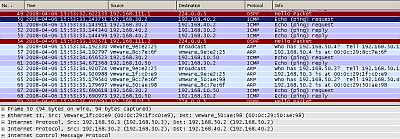
Figure94: Wireshark Capture IPIP Tunnels: Ping
Things look good.
All the configuration lines entered on Vyatta HQ, Vyatta Branch1 and Vyatta Branch2 can be found here:
- Vyatta HQ
- Vyatta Branch1
- Vyatta Branch2
8. IPIP - Make The hub-and-spoke Topology a Mesh One
If you want, you can make the hub-and-spoke topology a mesh one, by configuring an IPIP tunnel between Branch1 and Branch2.
On Branch1 add:
set interfaces tunnel tun2
set interfaces tunnel tun2 address 192.168.131.1/24
set interfaces tunnel tun2 description "IPIP Tunnel to Branch2"
set interfaces tunnel tun2 encapsulation ipip
set interfaces tunnel tun2 local-ip 192.168.50.3
set interfaces tunnel tun2 remote-ip 192.168.50.4
set protocols ospf area 100 network 192.168.131.0/24
On Branch2 add:
set interfaces tunnel tun2
set interfaces tunnel tun2 address 192.168.131.2/24
set interfaces tunnel tun2 description "IPIP Tunnel to Branch1"
set interfaces tunnel tun2 encapsulation ipip
set interfaces tunnel tun2 local-ip 192.168.50.4
set interfaces tunnel tun2 remote-ip 192.168.50.3
set protocols ospf area 100 network 192.168.131.0/24
In Part 7 we will use IPsec to protect the GRE tunnels on the Vyatta VC4 VMs for Scenario 1.
|