|
31.03.2008
Updated 23.04.2008
Vyatta VC4 - Advanced VPN Site-to-Site Connections - Part 2 - A Quick Overview in Pictures of Various Implementations from Different Vendors: GRE/IPsec, IPIP/IPsec, L2TP/IPsec, Cisco's SVTI and DMVPN
- 1. "Classic" VPN Site-to-Site Connection Using IPsec Tunnel Mode
- 2. Cisco's IPsec Virtual Tunnel Interface (VTI)s
- 3. Point-to-Point GRE Tunnels
- 4. Point-to-Point GRE Tunnels + IPsec: ESP in Transport Mode
- 5. Point-to-Point GRE Tunnels + IPsec: ESP in Tunnel Mode
- 6. IPIP Tunnels
- 7. IPIP Tunnels + IPsec: ESP in Transport Mode
- 8. IPIP Tunnels + IPsec: ESP in Tunnel Mode
- 9. L2TP/ IPsec: ESP in Transport Mode
- 10. Cisco's DMVPN
Let's analyze some data and see how it travels along the wire. Assume that we have the scenario from Figure1. Two routers, one subnet behind each router, the routers are directly connected(192.168.50.0/24). Actually if you wonder, the two routers are Cisco routers and not Vyatta VC4 machines. The reason behind this was to be able to take a look at Cisco's IPsec Static Virtual Tunnel Interfaces (SVTIs) and DMVPN. Taking all the Wireshark captures using the same equipment will keep things contiguous. The only exception was the L2TP/IPsec site-to-site connection where I've used two ISA 2006 Firewalls.
Figure1: Scenario
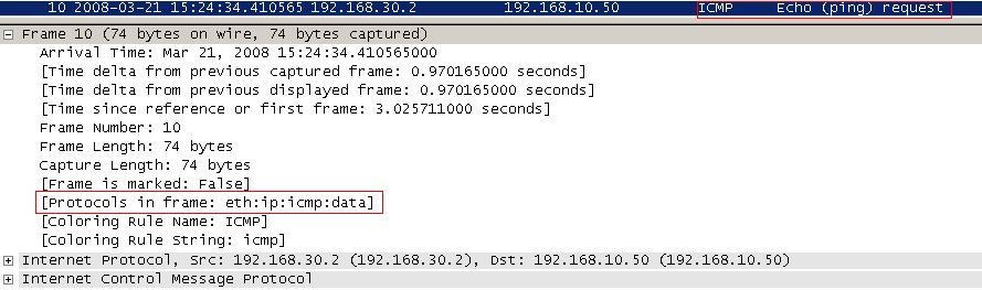
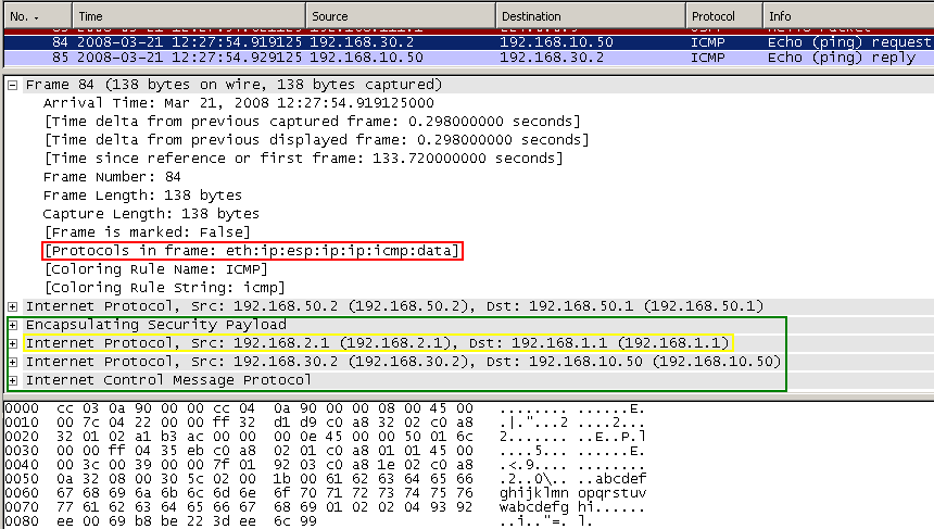
In order to generate some traffic, I've used the ping command. So a host behind R1 (located on the 192.168.30.0/24 subnet) wants to reach a host behind R0 (located on the 192.168.10.0/24 subnet) and vice-versa. R0's external IP address is 192.168.50.1 and R1's external IP address is 192.168.50.2. As usually, we will capture traffic with our favourite protocol analyzer, Wireshark. See Figure2.
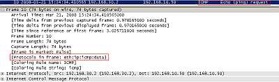
Figure2: Ping
1. "Classic" VPN Site-to-Site Connection Using IPsec Tunnel Mode
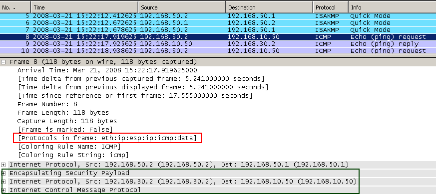
Using the classic or traditional approach we would create a site-to-site connection using IPsec tunnel mode ("basic" site-to-site connection) in order to securely pass the traffic between sites over the Internet. See Figure3.
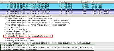
Figure3: Classic IPsec Tunnel Mode
As can be seen from Figure3 (IPComp is off) the entire packet including the original IP header has been encapsulated (look at the IPsec ESP Header) and a new IP header was appended (with the source and destination IP addresses of the VPN gateways).
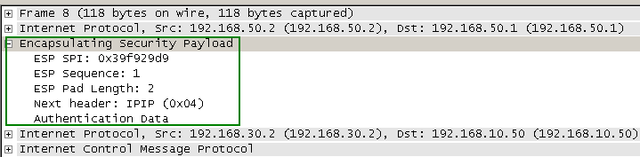
Actually, not clearly shown, after the ICMP field follows the ESP Trailer + the ESP Authentication Trailer. Wireshark groups them into the ESP field though, which contains the ESP header too. This aspect will be true for every picture which shows IPsec protected packets in this article. So keep that in mind. If you find that the number of bytes does not match (in case you do some estimations), note that the ESP Pad Length is 2 in every picture, except the one with L2TP/IPsec where is 1. Also, ESP confidentiality was set to NULL, and ESP integrity to HMAC-SHA-1-96 or HMAC-MD5-96 in case of L2TP/IPsec (the 96 number indicate that the Authentication Data field contains 96 bits, for example although HMAC-SHA-1-96 produces a 160-bit authenticator value, a truncated value is stored within the authenticator field: the first 96 bits).
The ESP header contains the following fields: SPI and Sequence Number.
The ESP trailer contains the following fields: Padding, Padding Length and Next Header.
The ESP authentication trailer contains the Authentication Data field. See Figure4 for the ESP field in Wireshark.
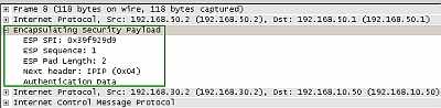
Figure4: Wireshark ESP Field
As said before, using the classic IPsec Tunnel Mode site-to-site connection creates various limitations.
2. Cisco's IPsec Virtual Tunnel Interface (VTI)s
In order to solve some of these limitations, an IPsec virtual tunnel interface can be implemented. So a routable interface for terminating IPsec tunnels and an easier way to define protection for the traffic between our sites can be provided. In Figure5 and Figure6 we can see Cisco's approach called IPsec Virtual Tunnel Interface (VTI), SVTI(Static VTI) in this case.
With IPsec VTI, IPsec ESP in Tunnel Mode is used (Proxy Identities are set to 0.0.0.0/0).
The IPsec SVTIs are limited to IP unicast and multicast traffic only.
In this case, I've defined the site-to-site connection between R0 and R1 using Static IPsec Virtual Tunnel Interfaces (VTIs), and instead of static routes, I've used OSPF to find out the networks behind the two Cisco routers.
The IP addresses ("ip address") of the "Tunnels" are 192.168.111.1 for R0's "interface Tunnel0" and respectively 192.168.111.2 for R1's "interface Tunnel0" (private IP addresses).
For R0 the "tunnel source" is 192.168.50.1 (the IP address of the local external physical interface, which in reality would be a public IP address - Internet routable address -) and the "tunnel destination" 192.168.50.2 (the IP address of the remote external physical interface, which in reality would be a public IP address - Internet routable address -). For R1 the "tunnel source" and "tunnel destination" will be reversed.
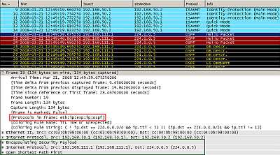
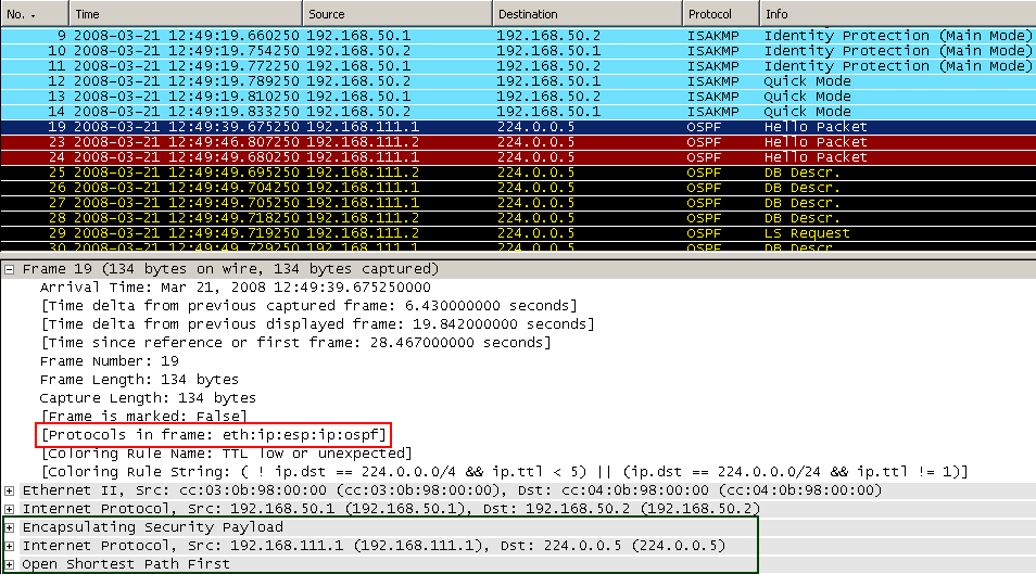
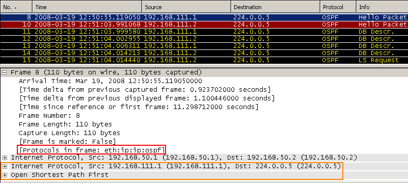
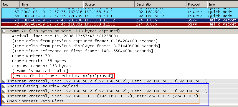
Figure5: Cisco's Static IPsec Virtual Tunnel Interface: OSPF packets
In Figure5 we can see the OSPF multicast packets flowing after IKE Phase I and II were completed, packets protected by ESP in tunnel mode. The entire message including the original IP header(as source IP addresses ("ip address") of the "Tunnel " and as destination the multicast address 224.0.0.5) has been encapsulated (note the IPsec ESP Header) and a new IP header was appended (with the source and destination IP addresses from the "tunnel source" and "tunnel destination ").
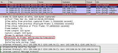
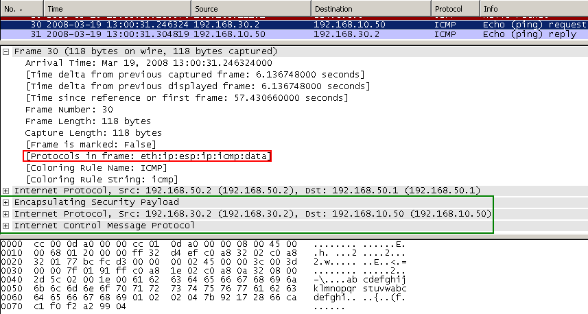
Figure6: Cisco's Static IPsec Virtual Tunnel Interface: Ping
In Figure6 we can see our ping packet. As can be noted we have no packet overhead compared to the "classic" tunnel mode (if your use DVTIs you will have +4 bytes of packet overhead due to a "VTI dummy" header). The entire packet including the original IP header has been encapsulated (see the IPsec ESP Header) using ESP in tunnel mode and a new IP header was appended (with the source and destination IP addresses from the "tunnel source" and "tunnel destination").
3. Point-to-Point GRE Tunnels
Now let's establish a GRE tunnel in clear (without IPsec protection) between our sites.
The IP addresses ("ip address") of the "Tunnels" are 192.168.111.1 for R0's "interface Tunnel0" and respectively 192.168.111.2 for R1's "interface Tunnel0" (private IP addresses).
For R0 the "tunnel source" is 192.168.50.1 (the IP address of the local external physical interface, which in reality would be a public IP address - Internet routable address -) and the "tunnel destination" 192.168.50.2 (the IP address of the remote external physical interface, which in reality would be a public IP address - Internet routable address -). For R1 the "tunnel source" and "tunnel destination" will be reversed.
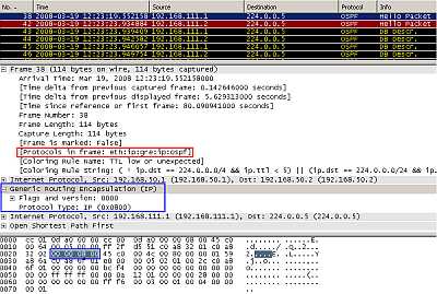
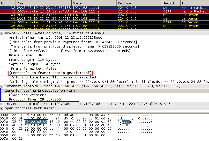
Figure7: Point-to-Point GRE Tunnel: encapsulated OSPF packets
In Figure7 we can see the OSPF multicast packets flowing inside the GRE tunnel.
So GRE will handle the transport of multicast traffic between our sites.
Because the multicast packet is encapsulated into a unicast packet, IPsec can now handle the resulted unicast packet.
The entire packet including the original IP header (as source IP addresses ("ip address") of the "Tunnel " and as destination the multicast address 224.0.0.5) has been encapsulated by GRE and a new IP header was appended ,with the source and destination IP addresses from the "tunnel source" and "tunnel destination", the IP addresses of the physical interfaces.
The "tunnel source" specifies which IP address on the local router will be used in the IP header of the GRE packet as the source IP address - from where the tunnel will be initiated -.
The "tunnel destination" specifies which IP address would be used in the IP header of the GRE packet as the destination IP address - where (the destination router) the GRE tunnel will be terminated.
In our case(not using IPsec) in practice, the "tunnel source" and "tunnel destination" addresses would be public IP addresses(Internet routable addresse). They can be addresses of physical or loopback router interfaces.
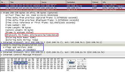
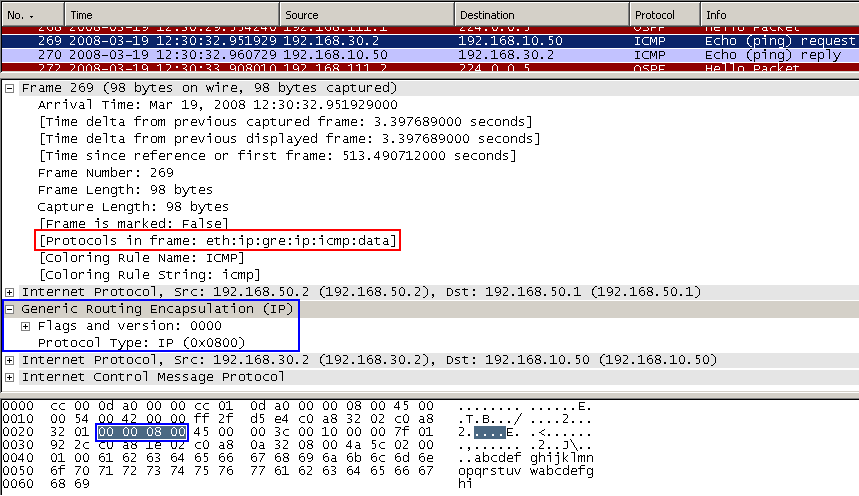
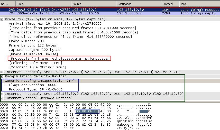
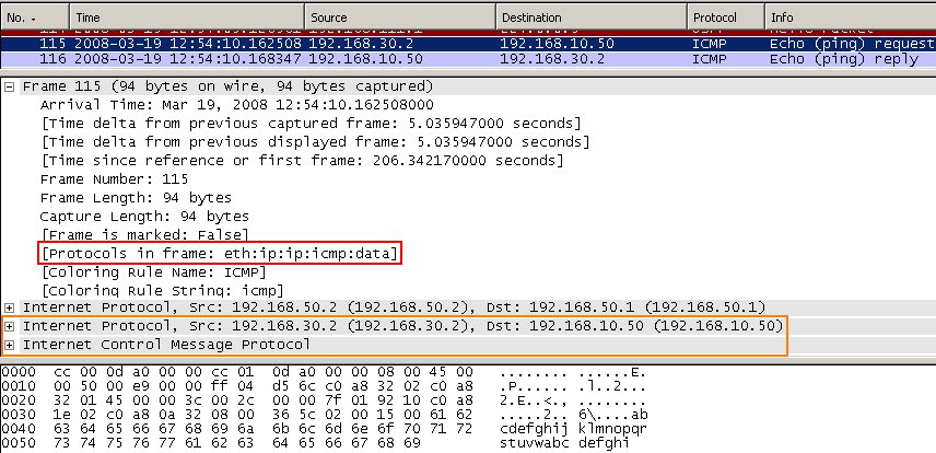
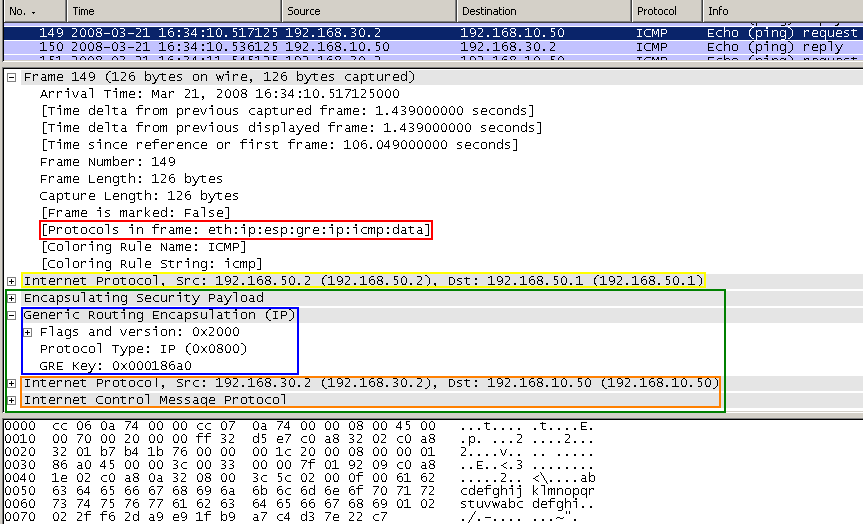
Figure8: Point-to-Point GRE Tunnel: Ping
In Figure8 we can see our ping packet inside the point-to-point GRE tunnel. The entire packet including the original IP header has been encapsulated by GRE and the new IP header was appended (with the source and destination IP addresses from the "tunnel source" and "tunnel destination").
Note the 4 byte GRE header.
4. Point-to-Point GRE Tunnels + IPsec: ESP in Transport Mode
As can be seen, the GRE tunnels are not protected. However, as said before, since now we are dealing with unicast packets, we can use IPsec to protect the GRE traffic.
It must be noted that the traffic between our sites will travel inside the GRE tunnels, so communications are host-to-host ones, we have a point-to-point connection. Therefore we can use IPsec in transport mode to protect the GRE packets. Using IPsec in tunnel mode may be unnecessary when both the GRE "tunnel source" and "tunnel destination " are public IP addresses and match the addresses of the IPsec VPN peers (for example we would use tunnel mode when "tunnel source" and "tunnel destination" addresses are private IP addresses belonging to loopback interfaces, scroll down to see that).
Traffic destined to the remote site will be encapsulated within the GRE tunnel, and the GRE packet will be encrypted(protected) at the external physical interface using IPsec ESP.
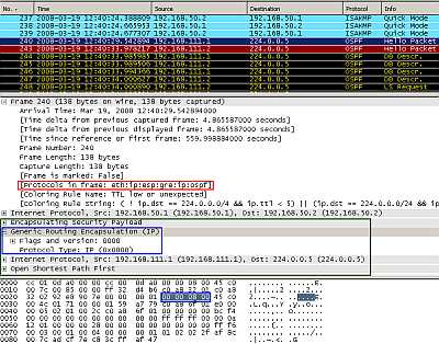
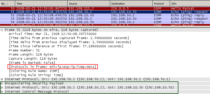
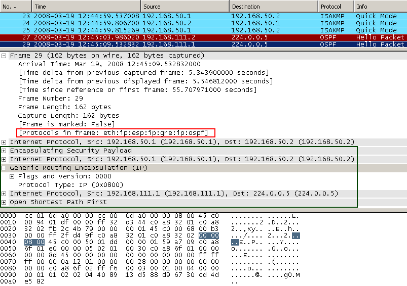
Figure9: Point-to-Point GRE Tunnel Protected by IPsec ESP In Transport Mode: OSPF traffic
As can be seen in Figure9 the multicast IP OSPF packet was encapsulated as above (Figure7) by GRE and a new IP header was appended. This new packet minus the new IP header is protected by IPsec ESP, note that the IPsec ESP header was introduced between the protected payload and the new IP header.
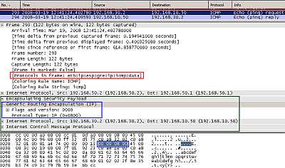
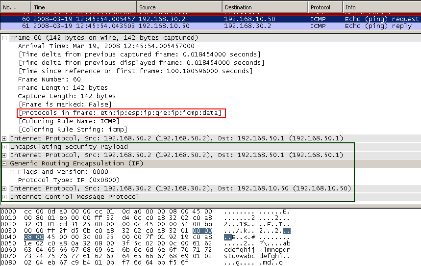
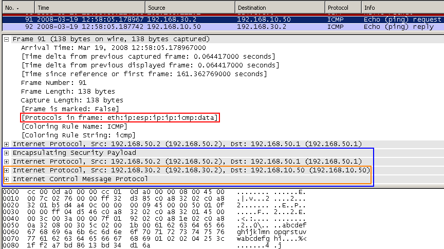
Figure10: Point-to-Point GRE Tunnel Protected by IPsec ESP In Transport Mode: Ping
In Figure10 the we can spot our ping packet. The ping packet was encapsulated as above(Figure8) by GRE and a new IP header was appended. This new packet minus the new IP header is protected by IPsec ESP, you can see the IPsec ESP header introduced between the protected payload and the new IP header.
So comparing the point-to-point GRE tunnel+IPsec in Transport Mode with the "classic" tunnel mode or with Cisco's SVTIs we have a 4 byte packet overhead resulted from the use GRE tunnel.
5. Point-to-Point GRE Tunnels + IPsec: ESP in Tunnel Mode
Let's use IPsec ESP in tunnel mode to protect the GRE tunnels.
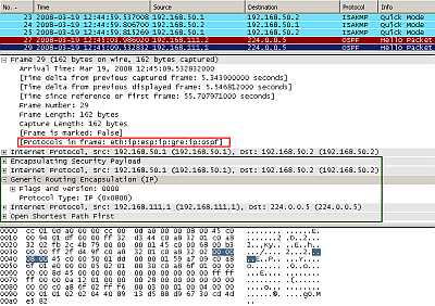
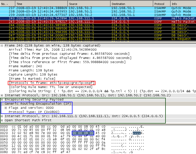
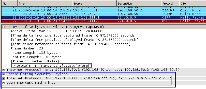
Figure11: Point-to-Point GRE Tunnel Protected by IPsec ESP In Tunnel Mode: OSPF traffic
As can be seen in Figure11 the multicast IP OSPF packet was encapsulated as above(Figure7 ) by GRE and a new IP header was appended. This entire new packet including the new IP header is protected by IPsec ESP and a new IP header is added, note the position of the IPsec ESP header.
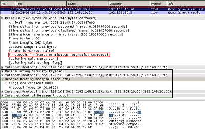
Figure12: Point-to-Point GRE Tunnel Protected by IPsec ESP In Tunnel Mode: Ping
In Figure12 the we can spot our ping packet. The ping packet was encapsulated as above(Figure8 ) by GRE and a new IP header was appended. This entire new packet including the new IP header is protected by IPsec ESP, note the position of the IPsec ESP header in this case.
So comparing the point-to-point GRE tunnel+IPsec in Tunnel Mode with the "classic" tunnel mode or with Cisco's VTIs we have an additional overhead(4 bytes + another 20 bytes for the new IP header).
As said before we can use for GRE tunnels as "tunnel source" and "tunnel destination " IP addresses from a loopback or physical interface. Typically both the addresses for "tunnel source" and "tunnel destination " and VPN IPsec peers are public IP addresses. And the "tunnel source " address matches the local address for the IPsec "tunnel". And the "tunnel destination" address matches the remote address for the IPsec "tunnel".
However, in case we set private IP addresses on the loopback interfaces and use them as "tunnel source" and "tunnel destination" then we would need IPsec ESP in tunnel mode instead of transport mode. The entire packet, including the new GRE IP header needs to be encapsulated and a new IP header will be added (likely containing the public IP addresses of the physical interfaces used as IPsec interfaces).
Let's visualize this.
The R0 router is using a loopback interface with the IP address 192.168.1.1, thus the GRE "tunnel source" will be 192.168.1.1.
The R1 router is using a loopback interface with the IP address 192.168.2.1, thus the GRE "tunnel source" will be 192.168.2.1.
On the R0 router, the "tunnel destination" is 192.168.2.1.
On the R1 router, the "tunnel destination" is 192.168.1.1.
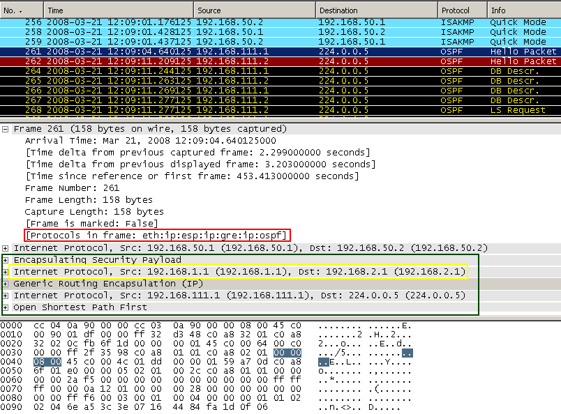
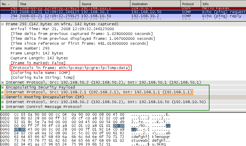
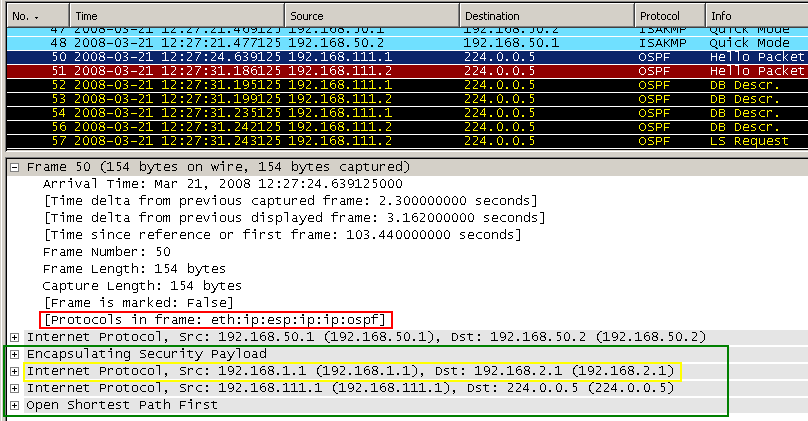
As can be seen in Figure13 and Figure14, the multicast IP OSPF and our ping packets were encapsulated by GRE and a new IP header was appended (this time we can clearly see the "tunnel source" and "tunnel destination "). This entire new packet including the new IP header is protected by IPsec ESP and a new IP header is added (with the IP addresses of the IPsec interfaces), note the position of IPsec ESP header. So we need IPsec ESP in tunnel mode in practice because 192.168.1.1 and 192.168.2.1 are private IP addresses, thus non Internet routable ones.
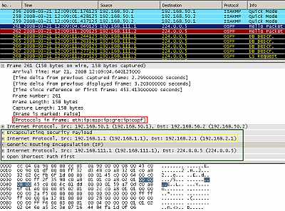
Figure13: Point-to-Point GRE Tunnel using as "tunnel source" and "tunnel destination" private IP addresses(from Loopback Interfaces) Protected by IPsec ESP In Tunnel Mode: OSPF traffic
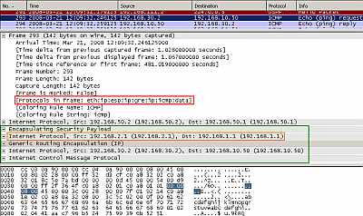
Figure14: Point-to-Point GRE Tunnel using as "tunnel source" and "tunnel destination" private IP addresses(from Loopback Interfaces) Protected by IPsec ESP In Tunnel Mode: Ping
6. IPIP Tunnels
Now let's establish an IPIP tunnel in clear (without IPsec protection) between our sites.
The IP addresses ("ip address") of the "Tunnels" are 192.168.111.1 for R0's "interface Tunnel0" and respectively 192.168.111.2 for R1's "interface Tunnel0" (private IP addresses).
For R0 the "tunnel source" is 192.168.50.1 (the IP address of the local external physical interface, which in reality would be a public IP address - Internet routable address -) and the "tunnel destination" 192.168.50.2 (the IP address of the remote external physical interface, which in reality would be a public IP address - Internet routable address -). For R1 the "tunnel source" and "tunnel destination" will be reversed.
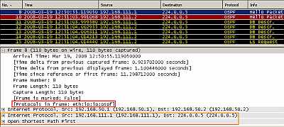
Figure15: IPIP Tunnel: OSPF traffic
In Figure15 we can see the OSPF multicast packets flowing inside the IPIP tunnel.
The entire packet including the original IP header (as source IP addresses ("ip address") of the "Tunnel " and as destination the multicast IP address 224.0.0.5) has been encapsulated and a new IP header was appended, with the source and destination IP addresses from the "tunnel source" and "tunnel destination", the IP addresses of the physical interfaces.
The "tunnel source " specifies which IP address on the local router will be used in the new IP header as the source IP address - from where the IPIP tunnel will be initiated -.
The "tunnel destination " specifies which IP address would be used in the new IP header as the destination IP address - where (the destination router) the IPIP tunnel will be terminated.
In our case(not using IPsec) in practice, the "tunnel source" and "tunnel destination" addresses would be public IP addresses(Internet routable addresse). They can be addresses of physical or loopback router interfaces.
Because the multicast packet is encapsulated into a unicast packet, IPsec can now handle the resulted unicast packet.
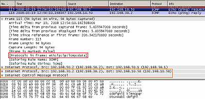
Figure16: IPIP Tunnel: Ping
In Figure16 we can see our ping packet inside the IPIP tunnel. The entire packet including the original IP header has been encapsulated and the new outer IP header was appended (with the source and destination IP addresses from the "tunnel source" and "tunnel destination").
7. IPIP Tunnels + IPsec: ESP in Transport Mode
Obviously we cannot send any important traffic over the Internet because the IPIP tunnels are unprotected.
However, since now we are dealing with unicast packets, we can use IPsec to protect the IPIP traffic.
As like in case of point-to-point GRE tunnels, the traffic between our sites will travel inside the tunnels, IPIP tunnels now. So communications are host-to-host ones, we have a point-to-point connection. Therefore we can use IPsec in transport mode to protect the packets.
Using IPsec in tunnel mode may be unnecessary when both the IPIP "tunnel source" and "tunnel destination" are public IP addresses and match the addresses of the IPsec VPN peers (for example we would use tunnel mode when "tunnel source" and "tunnel destination" addresses are private IP addresses belonging to loopback interfaces).
IP traffic destined to the remote site will be encapsulated within the IPIP tunnel, and the IPIP packet will be encrypted(protected) at the external physical interface using IPsec ESP.
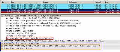
Figure17: IPIP Tunnel Protected by IPsec ESP In Transport Mode: OSPF traffic
As can be seen in Figure17 the multicast IP OSPF packet was encapsulated as in Figure15 and a new outer IP header was appended. This new packet minus the new IP header is protected by IPsec ESP, note that the IPsec ESP header was introduced between the protected payload and the new IP header.
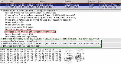
Figure18: IPIP Tunnel Protected by IPsec ESP In Transport Mode: Ping
In Figure18 we can spot our ping packet. The ping packet was encapsulated as in Figure16 and a new IP header was appended. This new packet minus the new IP header is protected by IPsec ESP, you can see the IPsec ESP header introduced between the protected payload and the new IP header.
So comparing the IPIP tunnel+IPsec in Transport Mode with the "classic" tunnel mode or with Cisco's VTIs we can notice that they "look" similar (no packet overhead).
8. IPIP Tunnels + IPsec: ESP in Tunnel Mode
Let's use IPsec ESP in tunnel mode to protect the IPIP tunnels.
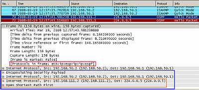
Figure19: IPIP Tunnel Protected by IPsec ESP In Tunnel Mode: OSPF traffic
As can be seen in Figure19 the multicast IP OSPF packet was encapsulated as in Figure15 and a new outer IP header was appended. This entire new packet including the new outer IP header is protected by IPsec ESP and a new IP header is added, note the position of the IPsec ESP header.
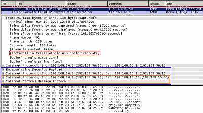
Figure20: IPIP Tunnel Protected by IPsec ESP In Tunnel Mode: Ping
In Figure20 the we can spot our ping packet. The ping packet was encapsulated as in Figure16 and a new outer IP header was appended. This entire new packet including the new outer IP header is protected by IPsec ESP, note the position of the IPsec ESP header in this case.
So comparing the IPIP tunnel+IPsec in Tunnel Mode with the "classic" tunnel mode or with Cisco's VTIs we have an additional overhead(another 20 bytes for the new IP header).
As said before we can use for IPIP tunnels as "tunnel source" and "tunnel destination " IP addresses from a loopback or physical interface. Typically both the addresses for "tunnel source" and "tunnel destination " and VPN IPsec peers are public IP addresses. And the "tunnel source " address matches the local address for the IPsec "tunnel". And the "tunnel destination" address matches the remote address for the IPsec "tunnel".
However, in case we set private IP addresses on the loopback interfaces and use them as "tunnel source" and "tunnel destination" then we would need IPsec ESP in tunnel mode instead of transport mode. The entire packet, including the new IP header needs to be encapsulated and a new IP header will be added (likely containing the public IP addresses of the physical interfaces used as IPsec interfaces).
Let's visualize this.
The R0 router is using a loopback interface with the IP address 192.168.1.1, thus the IPIP "tunnel source" will be 192.168.1.1.
The R1 router is using a loopback interface with the IP address 192.168.2.1, thus the IPIP "tunnel source" will be 192.168.2.1.
On the R0 router, the "tunnel destination" is 192.168.2.1.
On the R1 router, the "tunnel destination" is 192.168.1.1.
As can be seen in Figure21 and Figure22, the multicast IP OSPF and our ping packets were encapsulated in an IP datagram (this time we can clearly see the "tunnel source" and "tunnel destination "). This entire new packet including the new IP header is protected by IPsec ESP and a new IP header is added (with the IP addresses of the IPsec interfaces), note the position of IPsec ESP header. So we need IPsec ESP in tunnel mode in practice because 192.168.1.1 and 192.168.2.1 are private IP addresses, thus non Internet routable ones.
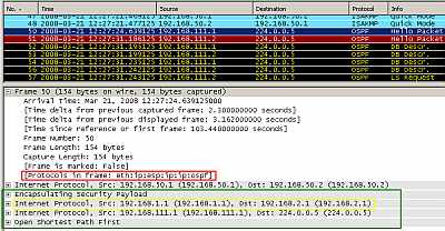
Figure21: IPIP Tunnel using as "tunnel source" and "tunnel destination" private IP addresses(from Loopback Interfaces) Protected by IPsec ESP In Tunnel Mode: OSPF traffic
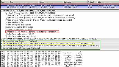
Figure22: IPIP Tunnel using as "tunnel source" and "tunnel destination" private IP addresses(from Loopback Interfaces) Protected by IPsec ESP In Tunnel Mode: Ping
9. L2TP/ IPsec: ESP in Transport Mode
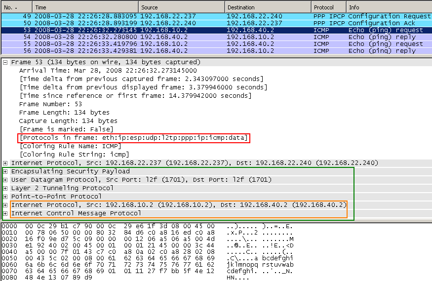
In Figure23 we can see a ping packet travelling between two sites inside the L2TP tunnel protected by IPsec ESP in Transport Mode (MPPC is off). We can notice that is quite heavily encapsulated. Also look at the position of the ESP header corresponding to IPsec ESP in Transport Mode. As said before, Microsoft does not seem eager to play the game of dynamic VPNs, I've entered manually the subnets behind the VPN gateways, so no OSPF here. Microsoft uses the second level of authentication (PPP authentication) too in addition to IKE authentication for L2TP/IPsec VPN site-to-site connections.
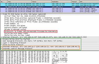
Figure23: L2TP/IPsec - ESP Transport Mode: Ping
10. Cisco's DMVPN
Let's take a quick look at Cisco's piece of engineering called DMVPN. For this let's imagine the simple scenario from Figure24 , single hub with two spokes. In this case, on the hub multipoint GRE will be used on the tunnel interface. Also on the spoke multipoint GRE will be used because the spoke will set up a connection to the other spoke (if only spoke-to-hub connectivity is needed, then on the spokes a point-to-point GRE tunnel can be used).
GRE will be used to transport routing traffic and data.
IPsec ESP in Transport Mode will be used to protect the GRE tunnels.
Some of Cisco's arguments for DMVPN are:
- P2P GRE tunnels+IPsec do not scale very well in case of full mesh designs.
- if there are many spokes, the configuration of the hub gets complicated, each P2P GRE tunnel+IPsec for each spoke must be manually configured on the hub.
- most often only spoke to hub connectivity is continuously required, and only from time to time, spoke to spoke connectivity.
- if spoke to spoke connectivity is required, then in a hub and spoke scenario, traffic between spokes will have to travel through the hub, causing some delay, and additional load on the hub system.
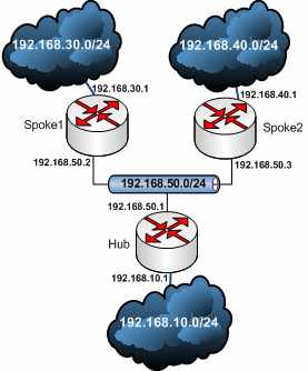
Figure24: Simple Cisco DMVPN Scenario
So in case of DMVPN, spokes are always connected and talk to the hub, on the hub there is a single multipoint GRE tunnel (no need for separate GRE tunnel interfaces anymore) and NHRP is added to the game.
With NHRP, systems attached to a NBMA network can dynamically learn the NBMA (physical) address of the other systems that are part of that network, allowing these systems to directly communicate.
Combining NHRP with IPsec, and the NBMA network is a collection of point-to-point logical tunnel links over a physical IP network (same with GRE tunnels, virtual tunnel networks).
For scalability reasons, multipoint interfaces - multipoint GRE tunnels in this case - can be used to reduce the configuration on the hub router.
As said before we setup a hub-and-spoke network.
The spokes are configured with static mapping information to reach their hub. They will connect to their hub and send a NHRP Registration Request.
This allows the hub to dynamically learn the mapping information for the spokes(the hub is configured with the "ip nhrp map multicast dynamic " command - when a spoke registers its unicast NHRP mapping with the hub, NHRP will also create a broadcast/multicast mapping for this spoke -), thus the configuration needed on the hub is reduced, and also allows the spoke to have a dynamic NBMA (physical) IP address (very useful for branch offices which may have a dynamic IP address).
If a spoke needs to communicate with another spoke, the spoke will send a NHRP query to the hub in order to find the physical address of the other spoke, and then a temporary VPN connections between the spokes will be created.
So NHRP is used for NHRP registration of the spokes(NHC) with the hub(NHS), and to enable the spokes to find a "shortcut path".
Thus, although our topology looks like a hub and spoke one, is actually a dynamic mesh topology (due to the dynamic spoke-to-spoke tunnels).
Let's exemplify this behaviour.
If a host located on 192.168.30.0/24 (behind Spoke1) needs to talk to a host located on 192.168.40.0/24 (behind Spoke2), the Spoke1 can to set up an IPsec connection to Spoke2 directly. For that, Spoke1 will send an NHRP query to the hub to find the physical address of the spoke responsible for the 192.168.40.0/24 network.
Note that Spoke1 knows about 192.168.40.0/24 from the hub, in this case OSPF was used to learn about it.
However Spoke1 knows the GRE tunnel "ip address" but does not know Spoke2's physical external interface address.
So the spoke will use NHRP to talk to the hub and find out the missing parameter.
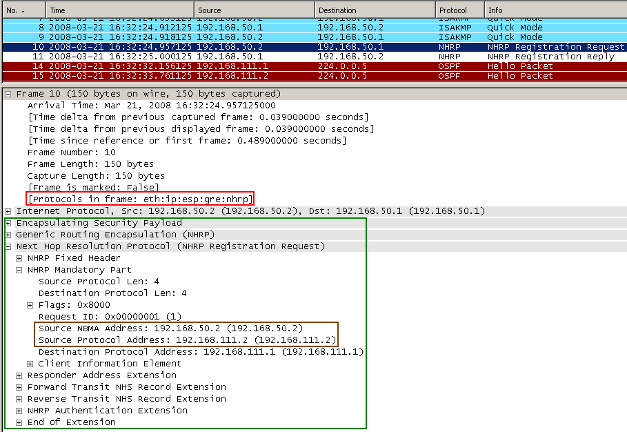
In Figure25 we can see Spoke1 initiating the VPN connection to the Hub (Spoke2 is turned off). After IKE MM and QM phases are completed, Spoke1 sends a NHRP Registration Request to the Hub. This enables the hub to dynamically learn the mapping information for the Spoke1, its physical address (192.168.50.2) associated with the the IP address ("ip address") of "interface Tunnel0 " from Spoke1 which is 192.168.111.2.
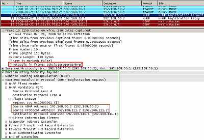
Figure25: Cisco's DMVPN: Spoke1 Initiates the VPN Connection to the Hub and Sends a NHRP Registration Request
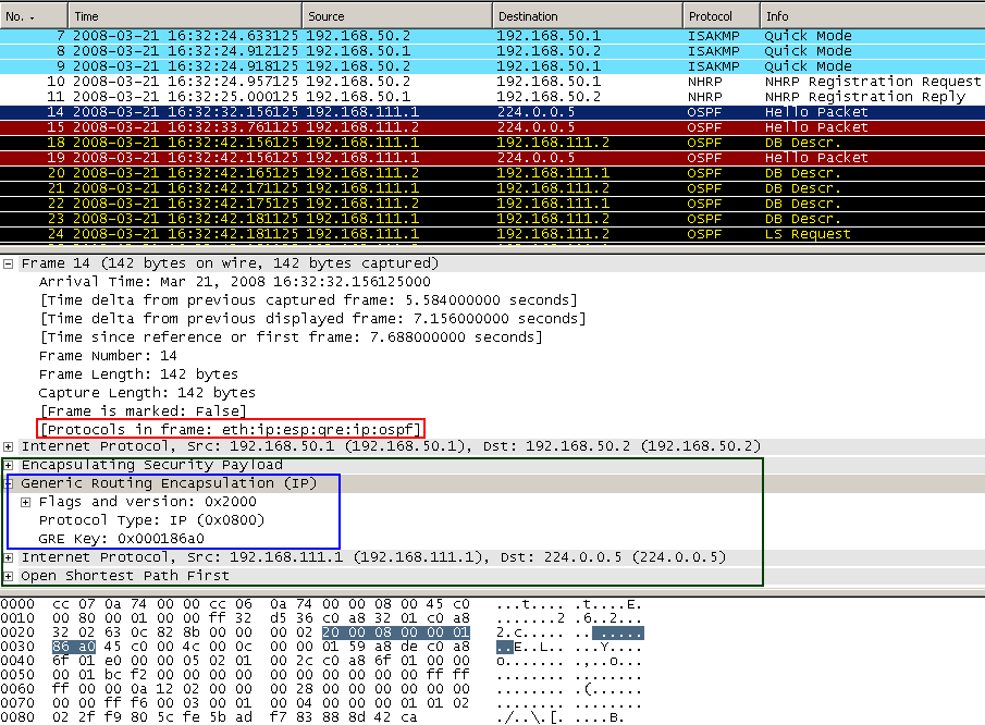
In Figure26 we can spot an OSPF multicast packet. After the NHRP Registration messages, the Hub and Spoke1 use OSPF to discover the network behind them. I've set the OSPF priority to 2 on the hub (to ensure that the hub becomes a DR ) and to 0 on the spokes (so a spoke will never become a DR) and the medium type is set to broadcast (on the tunnel interfaces: "ip ospf broadcast ").
As can be seen, now the GRE header has 8 bytes, due to the presence of the GRE tunnel key.
So, compared to the classical IPsec Tunnel Mode VPN site-to-site connection we have +8 bytes of packet overhead. Note that IPsec ESP Transport Mode is used.
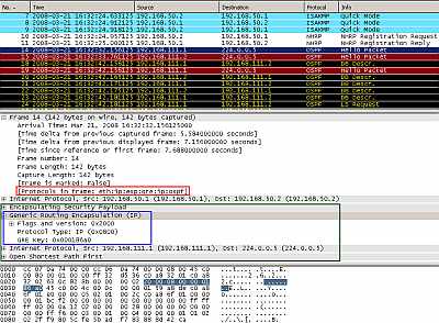
Figure26: Cisco's DMVPN: OSPF Traffic between the Hub and the Spoke
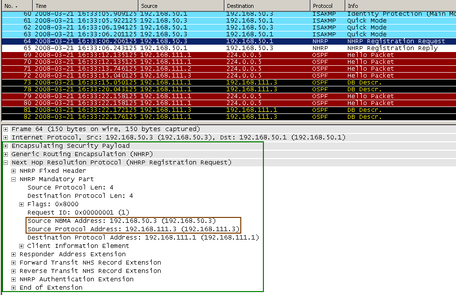
In Figure27 we can see Spoke2 initiating the VPN connection to the Hub (Spoke1 is up an running now). The process is the same as with Spoke1. After IKE MM and QM phases are completed, Spoke2 sends a NHRP Registration Request to the Hub. This enables the hub to dynamically learn the mapping information for the Spoke2, its physical address (192.168.50.3) associated with the the IP address ("ip address") of "interface Tunnel0" from Spoke2 which is 192.168.111.3.
Also now, Spoke2 will find out about the network behind Spoke1, and Spoke1 will find out about the network behind Spoke2.
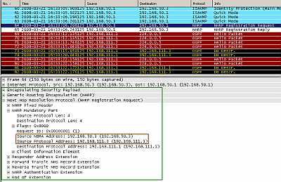
Figure27: Cisco's DMVPN: Spoke2 Initiates the VPN Connection to the Hub and Sends a NHRP Registration Request
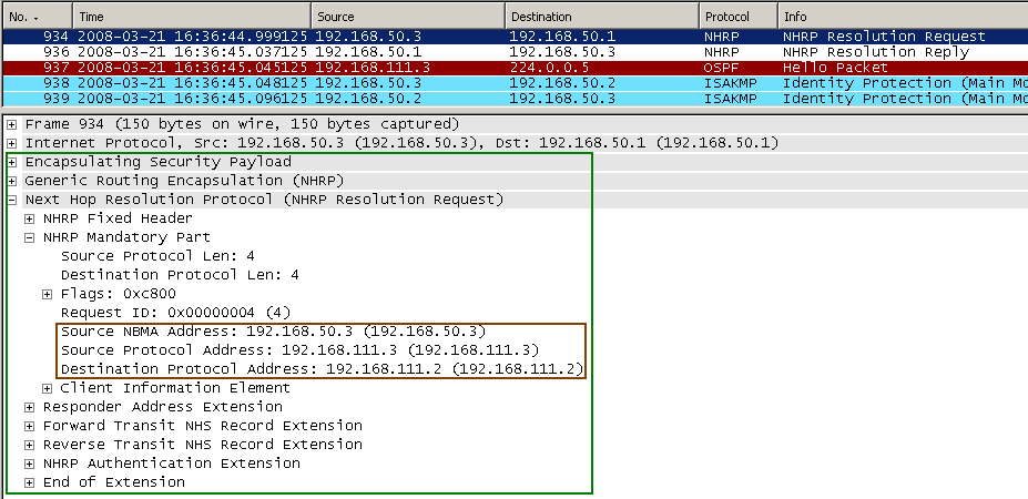
Normally, in a hub and spoke arhitecture, hosts behind the two spokes will talk to each other through the hub. However, using NHRP, Spoke2 can find out the physical address of Spoke1 and initiate a VPN connection to it, see Figure28. Actually, hosts' traffic will transit through the hub until the spoke-to-spoke connection is created. Spoke2 is aware that network 192.168.30.0/24 is accessible through 192.168.111.2 (it has learnt that through OSPF). But needs the physical address of Spoke1 (the IP address of the IPsec peer) in order to establish an IPsec session with Spoke1.
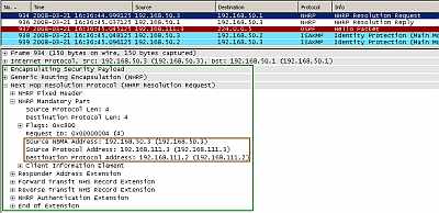
Figure28: Cisco's DMVPN: Spoke2's NHRP Resolution Request to Hub for Spoke1's Physical Address
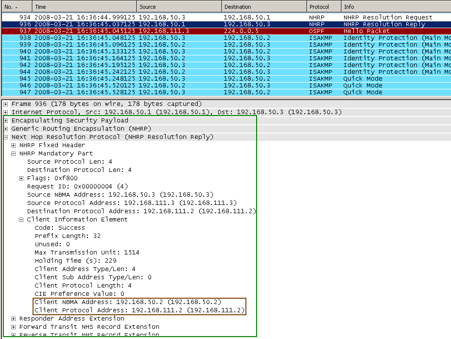
And the hub replies to the NHRP Resolution Request of Spoke2 with the physical address of Spoke1 (192.168.50.2), see Figure29.
Now, since it knows the physical address of Spoke1, Spoke2 initiates a VPN connection to it in order to pass traffic destined to it directly and not through the hub. After it has been idle for a specified amount of time, this connection will be terminated, in order to save resources.
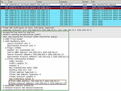
Figure29: Cisco's DMVPN: The Hub's NHRP Resolution Reply to Spoke2 for Spoke1's Physical Address
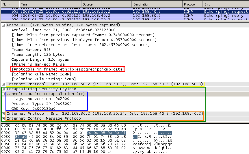
In Figure30 we can see a host behind Spoke1 talking to a host behind Spoke2 (a ping packet). We can notice that traffic is no longer redirected through the hub, instead the direct connection is used.
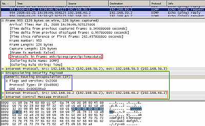
Figure30: Cisco's DMVPN: Ping from a host behind Spoke1 to a host behind Spoke2
And finally, in Figure30 we can see the ping packet we have followed throughout this article. As said before, we have +8 byte packet overhead compared to the standard IPsec Tunnel Mode site-to-site connection. But this may be just a minor detail compared with what can be achieved with DMVPN.
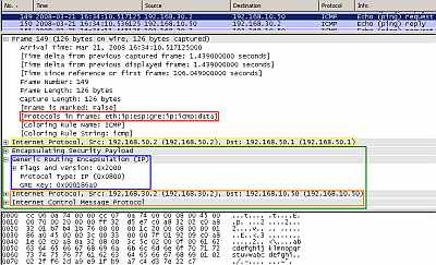
Figure31: Cisco's DMVPN: Ping from a host behind Spoke1 to a host behind Hub
In Part 3 we will start building our VMware lab and in the following parts test some advanced VPN site-to-site configurations between Vyatta VC4 machines and try to interoperate with a Cisco router.
|