|
22.07.2009
Configure an IPsec Tunnel Mode Site-to-Site VPN Between a Vyatta VC5 and a Cisco Router
1. Intro
2. Configuration Example
1. Intro
In this article we will configure an IPsec tunnel mode site-to-site between a Vyatta VC5 and a Cisco router running Cisco IOS.
I've decided to put the commands used to configure the two routers in a table, to have them side-by-side.
2. Configuration Example
Figure1 and Figure2 show the network diagrams for this lab:
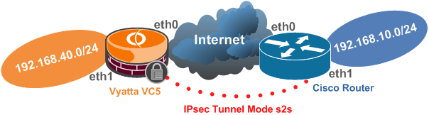
Figure1: Basic Network Diagram
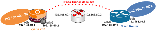
Figure2: Detailed Network Diagram of the Test Lab
Note that the IP addresses from Vyatta's eth0 interface and Cisco's f0/0 interface are considered to be public IP addresses within the bellow configuration(the IP addresses from these interfaces serve as IPsec VPN endpoints).
We will also configure NAT in order to enable the clients behind Vyatta and respectively Cisco to access the Internet.
So we will have to make sure that we exclude the s2s traffic from the NAT process.
On Vyatta we will configure a masquerade NAT rule and on Cisco we will configure NAT using overload(we have assumed that there is only a single public IP address on the external interface).
The bellow example only covers basic features. Please refer to each vendor's documentation for further details.
Vyatta's VCx documentation can be found here.
You can search for your specific Cisco router model at Cisco's web site (Cisco has a "habit" from moving and re-moving documents on its web site, so I will avoid posting links that sooner or later may cease to exist).
|
user@router:~$ ----> user@router#
(from Operational Mode to Configuration Mode)
configure
|
router# ----> router(config)#
(from Privileged Mode to Configuration Mode)
configure terminal
|
|
Configure the ethernet interfaces:
set interfaces ethernet eth0 address 192.168.60.2/24
set interfaces ethernet eth1 address 192.168.40.1/24
commit
|
Configure the ethernet interfaces:
interface f0/0
ip address 192.168.50.1 255.255.255.0
exit
interface f1/0
ip address 192.168.10.1 255.255.255.0
exit
|
|
Configure a default route:
set protocols static route 0.0.0.0/0 next-hop 192.168.60.1
commit
|
Configure a default route:
ip route 0.0.0.0 0.0.0.0 192.168.50.2
|
|
ConfigureNAT.
Exclude s2s traffic from the NAT process:
edit service nat rule 10
set type masquerade
set source address 192.168.40.0/24
set destination address 192.168.10.0/24
set outbound-interface eth0
set exclude
top
NAT Maquerade:
edit service nat rule 20
set type masquerade
set source address 192.168.40.0/24
set outbound-interface eth0
top
commit
|
Configure NAT.
Set NAT outside and inside interfaces:
interface f0/0
ip nat outside
exit
interface f1/0
ip nat inside
exit
NAT using overload(note that we exclude s2s traffic
from the NAT process within access list 111 using the
deny parameter):
ip nat inside source list 111 interface FastEthernet0/0 overload
access-list 111 deny ip 192.168.10.0 0.0.0.255 192.168.40.0 0.0.0.255
access-list 111 permit ip 192.168.10.0 0.0.0.255 any
|
|
Configure the IPsec tunnel mode s2s.
Enable ipsec vpn on the desired interface:
set vpn ipsec ipsec-interfaces interface eth0
Specify the IKE MM Policy:
edit vpn ipsec ike-group ciscoike proposal 1
set encryption aes128
set hash sha1
set dh-group 5
top
set vpn ipsec ike-group ciscoike lifetime 28800
Specify the IKE QM Policy(ESP tunnel mode is used by
default, also PFS for keys(QM) is enabled by default):
edit vpn ipsec esp-group ciscoesp proposal 1
set encryption aes128
set hash sha1
top
set vpn ipsec esp-group ciscoesp pfs enable
set vpn ipsec esp-group ciscoesp lifetime 3600
Create a vpn ipsec site-to-site for the remote peer,
specifying the authentication method, the IKE MM and
QM policies to be used and the traffic to be protected:
edit vpn ipsec site-to-site peer 192.168.50.1
set authentication mode pre-shared-secret
set authentication pre-shared-secret 12345
set ike-group ciscoike
set local-ip 192.168.60.2
edit tunnel 1
set local-subnet 192.168.40.0/24
set remote-subnet 192.168.10.0/24
set esp-group ciscoesp
top
commit
|
Configure the IPsec tunnel mode s2s.
Specify the ISAKMP Policy:
crypto isakmp policy 25
hash sha
encr aes 128
group 5
lifetime 28800
authentication pre-share
exit
Match the remote peer with its pre-shared secret:
crypto isakmp key 12345 address 192.168.60.2
Specify the IKE QM Policy(ESP tunnel is used by
default):
crypto ipsec transform-set vyattaset esp-aes 128 esp-sha-hmac
exit
Define with a crypto ACL the protected traffic:
access-list 101 permit ip 192.168.10.0 0.0.0.255 192.168.40.0 0.0.0.255
Bind with a crypto map all the crypto parameters with the
remote gateway:
crypto map vyatta 50 ipsec-isakmp
set peer 192.168.60.2
set transform-set vyattaset
match address 101
set pfs group5
exit
Apply the crypto map to the desired interface:
interface f0/0
crypto map vyatta
exit
|
|
|
|
|
Show the running configuration:
show -all |
Show the running configuration:
router(config)# ----> router#
(from Privileged Mode to Configuration Mode)
exit
show run
|
|
Save the current configuration(the configuration will be
saved to the config.boot file if we do not specify another
file):
save |
Save the running configuration to the startup configuration
(running-config(DRAM) to startup-config(NVRAM)):
copy run start
|
|
Show the IKE MM and IPsec SAs.
user@router# ----> user@router:~$(from Configuration
Mode to Operational Mode)
exit
show vpn ike sa
show vpn ipsec sa
|
Show the IKE MM and IPsec SAs:
show crypto isakmp sa
show crypto ipsec sa
|
|
View IPsec VPN debug information:
show vpn debug
|
Enable IKE and IPsec debugging in IOS(disable it by
a "no" in front of the bellow commands):
debug crypto isakmp
debug crypto ipsec
|
|
Test connectivity from the router itself:
/bin/ping -I 192.168.40.1 -c 4 192.168.10.1
|
Test connectivity from the router itself(use the extended
command):
ping
Protocol [ip]:
Target IP address: 192.168.40.1
Repeat count [5]:
Datagram size [100]:
Timeout in seconds [2]:
Extended commands [n]: y
Source address or interface: 192.168.10.1
Type of service [0]:
Set DF bit in IP header? [no]:
Validate reply data? [no]:
Data pattern [0xABCD]:
Loose, Strict, Record, Timestamp, Verbose[none]:
Sweep range of sizes [n]:
|
|