|
13.05.2008
Vyatta OFR Remote Access VPN - Part 1: PPTP
- 1. Intro
- 2. Basic Configuration
- 3. Local Users: Configuration
- 4. Local Users: Testing
- 5. Radius Authentication: Configuration
- 6. Radius Authentication: Testing
- 7. Radius Authentication - Some IAS Tricks
- 8. Support for Multiple PPTP Clients Located Behind the Same NAT Device at a Time
- 9. Quick Firewall Configuration: Intro
- 10. Quick Firewall Configuration: Local Firewall Instance on eth1
- 11. Quick Firewall Configuration: Local Firewall Instance on eth0
- 12. Quick Firewall Configuration: In Firewall Instance on eth1
- 13. Quick Firewall Configuration: In Firewall Instance on eth0
- 14. Quick Firewall Configuration: Out Firewall Instance on eth1
- 15. Quick Firewall Configuration: Out Firewall Instance on eth0
- 16. Quick Firewall Configuration: Testing
1. Intro
I'm not a PPTP fan (I do not like it at all), but since I've noticed that some people may want to use it, here we go.
PPTP is easy to set up. It can represent a convenient VPN protocol for some people. A company can have in no time with minimal effort a functional remote access VPN server. However, all these benefits come at a big cost regarding security.
Note: Make sure you use complex and long passwords for your PPTP users. PPTP's encryption and authentication will be as strong as users' passwords.
PPTP is not listed as a secure VPN technology supported by the VPN Consortium:
VPN Technologies: Definitions and Requirements
If you are concerned if PPTP is the right remote access VPN technology for you, you may like to read:
- Bruce Schneier's PPTP Web page
- Exploiting known security holes in Microsoft's PPTP Authentication Extensions (MS-CHAPv2) by Jochen Eisinger
- NIST Special Publication 800-77 - Guide to IPsec VPNs: Chapter 5. Alternatives to IPsec - 5.1 Data Link Layer VPN Protocols
In this part we will enable the PPTP VPN Server on Vyatta VC4, providing secure access (as secure as PPTP can be) to the corporate network and applications. See Figure1.
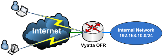
Figure1: Scenario
Figure2 presents the network diagram used in this part. Vyatta is behind a router (this is not a NAT device, it simply routes packets).
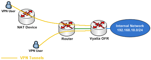
Figure2: Network Diagram
2. Basic Configuration
First I will configure Vyatta's interfaces and enable SSH. Then I can use a SSH client to quickly enter the rest of the configuration lines (I will copy and paste them):
set interfaces ethernet eth0 address 192.168.30.2/24
set interfaces ethernet eth1 address 192.168.10.1/24
set service ssh protocol-version 2
commit
Configure a default route, a DNS server for the router (a local DNS server located on the internal network) and a NAT rule:
set protocols static route 0.0.0.0/0 next-hop 192.168.30.1
set system name-server 192.168.10.2
set service nat rule 10 type masquerade
set service nat rule 10 source address 192.168.10.0/24
set service nat rule 10 outbound-interface eth0
commit
So now users behind Vyatta can access Internet hosts. Note that there is no firewall rule in place at this moment.
3. Local Users: Configuration
You can authenticate users locally on Vyatta if you don't want to use a RADIUS server for authentication.
If you have a few VPN users, you do not really need RADIUS authentication, unless you want to keep the authentication centralized (note that the local user's passwords are stored in clear on Vyatta, so this can be another reason to use RADIUS authentication).
Enabling the PPTP VPN Server on Vyatta with local authentication is straightforward:
- we need a pool of IP addresses (IP addresses that will be assigned through IPCP to the VPN clients, in our case the range of IP addresses is part of the internal network - on-subnet IP addresses -).
- set the authentication mode to local.
- define a couple of local users with their respective passwords (remember that the paswords will be stored in clear, so when someone issues for example the "show vpn pptp remote-access" command, he/she will see the passwords).
- enter the DNS and WINS servers for the VPN clients.
- and specify the IP address on which the PPTP service is listening (in our case this will be the IP address from the external interface, VPN clients will connect to this IP address).
set vpn pptp
set vpn pptp remote-access client-ip-pool start 192.168.10.220
set vpn pptp remote-access client-ip-pool stop 192.168.10.230
set vpn pptp remote-access authentication mode local
set vpn pptp remote-access authentication local-users username adrian password 1qaz
set vpn pptp remote-access dns-servers server-1 192.168.10.2
set vpn pptp remote-access wins-servers server-1 192.168.10.2
set vpn pptp remote-access outside-address 192.168.30.2
commit
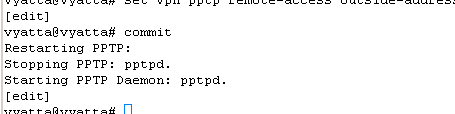
Figure3: Starting the PPTP Daemon
Note that as writing this, you cannot specify the user authentication methods on Vyatta from the CLI, but ms-chapv2 is required, as well as MPPE 128 bit, see Figure4, so this should not be a problem since the correct settings are in place by default.
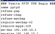
Figure4: Options.pptpd
4. Local Users: Testing
Time to make a test. I will create a VPN connection from a Windows XP SP3 machine(please read kb305550).
Let's quickly look at the created VPN connection.
The IP addresss of the VPN Server, see Figure5.
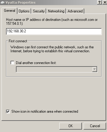
Figure5: VPN Connection Properties - The General Tab
The authentication settings are the default ones, see Figure6.
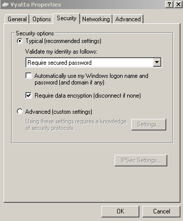
Figure6: VPN Connection Properties - The Security Tab
The VPN type will be PPTP, see Figure7. Note that compression (MPPC) is not used on Vyatta.
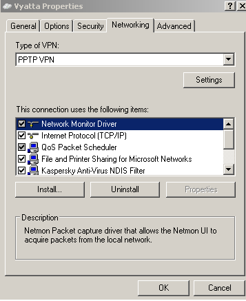
Figure7: VPN Connection Properties - The Networking Tab
Also split tunneling is disabled, the "Use default gateway on the remote network" checkbox is checked. See Figure9 , Figure10 and Figure11. Split tunneling, although appears appealing, introduces certain security risks, so you should leave that checkbox checked. Another thing that your VPN users may do for some ambiguous reasons, is to put a checkmark into "Allow other network users to connect through this computer’s Internet connection", see Figure8. This is also wrong. Vyatta, as currently writing, has no endpoint compliancy capabilities to ensure that split tunneling will not be enabled by the user and that ICS is not running, so at a minimum, you will have to make sure that VPN users are provisioned with a properly configured VPN connection. If you want to find out more about split tunneling, you may like to read (it's a bit off-topic since we are talking about PPTP here, but it will give you an idea about split tunneling) NIST Special Publication 800-77 - Guide to IPsec VPNs: 4.2.1.2 IPsec Client Software for Hosts, the lines about split tunneling. And also to read this.
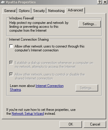
Figure8: VPN Connection Properties - The Advanced Tab
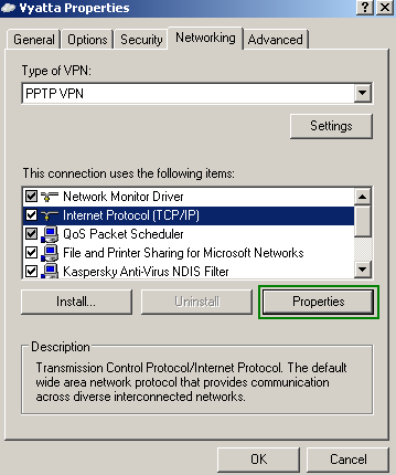
Figure9: VPN Connection Properties - The Networking Tab
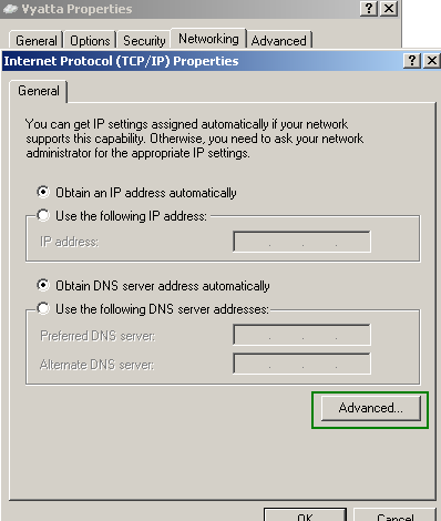
Figure10: VPN Connection Properties: TCP/IP Properties
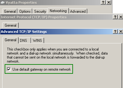
Figure11: VPN Connection Properties - No Split Tunneling
I will enter my credentials and click the Connect button, see Figure12.
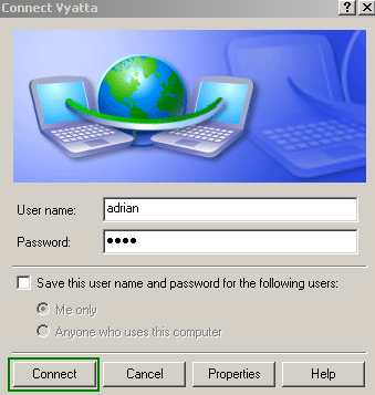
Figure12: Vyatta VPN Connection - Click The Connect Button
And I'm connected, see Figure13. The authentication method used is ms-chapv2 and the encryption method is MPPE 128 bit.
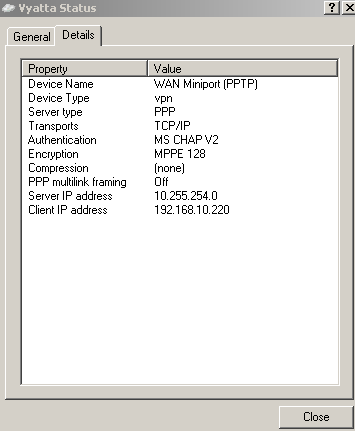
Figure13: Vyatta VPN Connection Status
As can be noticed, I've received for my PPP adapter, the 192.168.10.220 IP address. I can use the "ipconfig /all" command to view the IP settings for the PPP adapter, see Figure14.
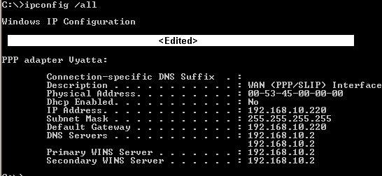
Figure14: ipconfig /all
I will do some connectivity checks now, to test if I can reach through the VPN tunnel a server located behind Vyatta. First a ping test. Note that I'm using a single-label hostname, I can do that because I have specified a WINS server. However, my machine has the Primary DNS Suffix set to carbonwind.net, so in this case, DNS name resolution will be used to resolve the server name (the DNS Suffix will be appended to the single-label hostname, thus a FQDN will be resolved by the internal DNS server 192.168.10.2, you may like to read KB311218, for some issues with the incorrect DNS server being used instead of the one from the PPP adapter). See Figure15.
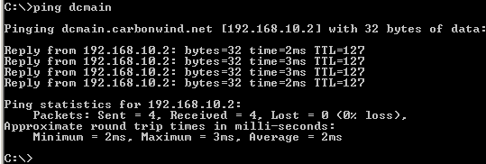
Figure15: Ping dcmain
So DNS name resolution is working and I have connectivity. I've also checked to see if I can access file shares, an internal web server and so on. Things looked good.
On Vyatta, let's view some information about the currently active remote access VPN sessions, see Figure16.
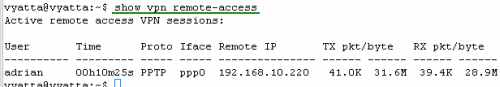
Figure16: show vpn remote-access
5. Radius Authentication: Configuration
You can authenticate users against a RADIUS server.
I will use IAS, Microsoft's RADIUS Server, please read this Microsoft doc for more details, Dial-up and VPN remote access. The IAS server is Active Directory integrated (it's actually installed on the DC). Because the IAS server is Active Directory integrated, I can keep the authentication centralized. Also since VPN users will use their domain accounts, I can force a strong password policy, do not forget that the password's strength is a very sensitive subject regarding PPTP.
Enabling the PPTP VPN Server on Vyatta with RADIUS authentication is straightforward too:
- we need a pool of IP addresses (IP addresses that will be assigned through IPCP to the VPN clients, in our case the range of IP addresses is part of the internal network - on-subnet IP addresses).
- set the authentication mode to radius.
- specify the IP address of the RADIUS server along with the password for the RADIUS server (the shared secret you've entered on the IAS server for Vyatta)
- set the DNS and WINS servers for the VPN clients.
- and specify the IP address on which the PPTP service is listening (in our case this will be the IP address from the external interface, VPN clients will connect to this IP address).
set vpn pptp
set vpn pptp remote-access client-ip-pool start 192.168.10.220
set vpn pptp remote-access client-ip-pool stop 192.168.10.230
set vpn pptp remote-access authentication mode radius
set vpn pptp remote-access authentication radius-server 192.168.10.2 key 12345
set vpn pptp remote-access dns-servers server-1 192.168.10.2
set vpn pptp remote-access wins-servers server-1 192.168.10.2
set vpn pptp remote-access outside-address 192.168.30.2
commit
Figure17: Starting the PPTP Daemon
In Active Directory, I've created a group, caled "VPNUsers", and made the domain users which need VPN remote access members of this group. I will use this group in the Remote Access Policy I will define on the IAS server.
For example, Diana, is a member of this group, see Figure18.
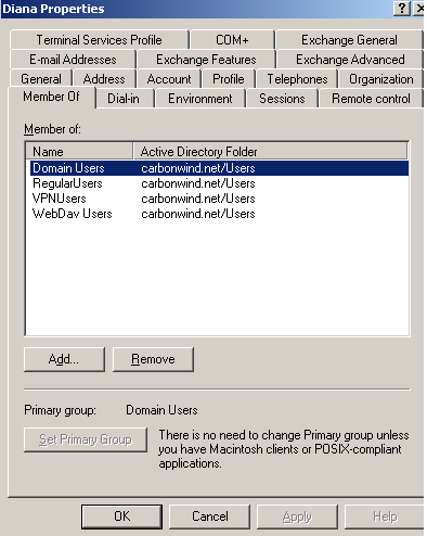
Figure18: Active Directory - Diana Properties: Member Of Tab
Also check the Dial-in tab, to make sure that Remote Access Permission (Dial-in or VPN) are not set to Deny access, see Figure19.
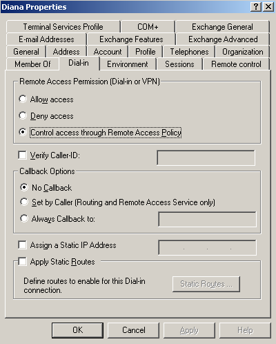
Figure19: Active Directory - Diana Properties: Dial-In
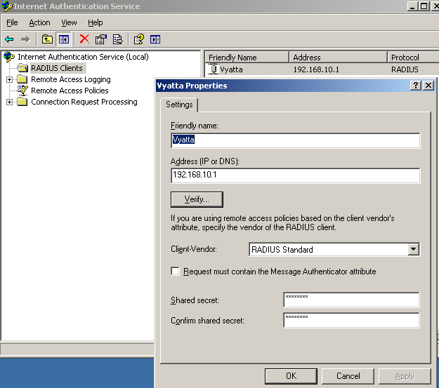
On the IAS server, I've added a RADIUS client called Vyatta (please read this Microsoft doc, Add RADIUS clients), see Figure20.
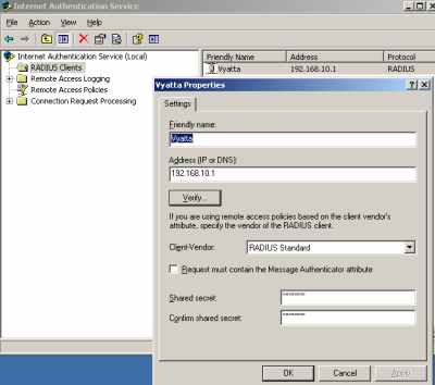
Figure20: IAS RADIUS Client
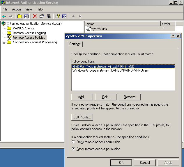
And I've created a typical VPN Remote Access Policy for a group of VPN users using the wizard (right-click "Remote Access Policies", click "New Remote Access Policy" and follow the wizard, select "Use the wizard to set up a typical policy for a common scenario", choose "VPN", add the "VPNUsers" group ..., please read this Microsoft doc for more details, Force VPN clients to use strongest encryption). However, there is a problem with this Remote Access Policy, it contains the NAS-Port-Type condition, see Figure21. And Vyatta, as a RADIUS client, does not send this attribute.
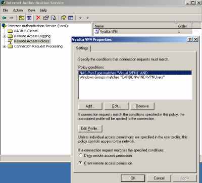
Figure21: Typical VPN Remote Access Policy
So I need to delete this attribute, see Figure22.
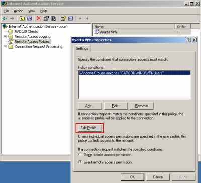
Figure22: Modified VPN Remote Access Policy
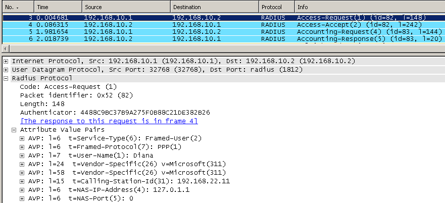
In Figure23 we can see the attributes sent by Vyatta to the RADIUS server.
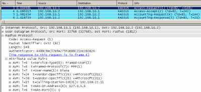
Figure23: Wireshark Capture: RADIUS messages
The VPN Remote Access Policy specifies as allowed authentication method only ms-chapv2, see Figure 24 (to access the "Edit Dial-in Profile" window, click the Edit Profile button from Figure22).
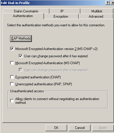
Figure24: VPN Remote Access Policy: User Authentication Methods
In the Encryption tab of the Edit Dial-in Profile, only the strongest encryption is allowed (MPPE 128 bit), see Figure25.
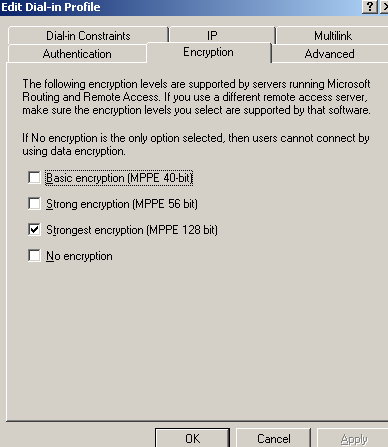
Figure25: VPN Remote Access Policy: Encryption Tab
In the Advanced tab of the Edit Dial-in Profile, see Figure26, we can notice the connection attributes Service-Type set to Framed and the Framed-Protocol set to PPP (these atributes are sent by Vyatta to the RADIUS server, take a look at Figure23). These attributes were configured by default when running the typical VPN Remote Access Policy wizard.
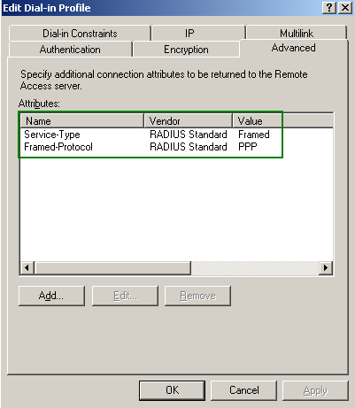
Figure26: VPN Remote Access Policy: Advanced Tab
6. Radius Authentication: Testing
Now I will connect with the user Diana to test my config. And I'm connected, see Figure27.
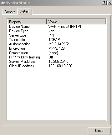
Figure27: Vyatta VPN Connection Status
I will do the ping connectivity check, to test if I can reach through the VPN tunnel a server located behind Vyatta. Again before I'm using a single-label hostname. See Figure28.
Figure28: Ping dcmain
So DNS resolution is working and I have connectivity. I can proceed and do further tests.
On Vyatta, let's view some information about the currently active remote access VPN sessions, see Figure29.
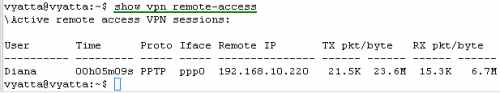
Figure29: show vpn remote-access
7. Radius Authentication - Some IAS Tricks
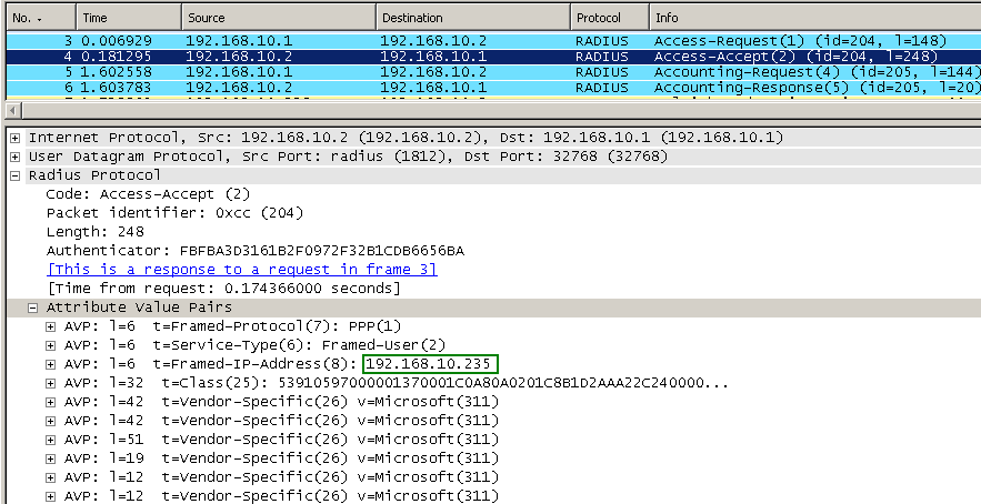
When you authenticate users against the IAS server, you can specify what IP address will be assigned to a specific user, see Figure30. This is useful when you may want to apply firewall rules to restrict access for certain users. It may be not very scalable though. Actually, as can be seen, I've assigned to Diana an IP address, 192.168.10.235, which is not from the pool configured on Vyatta. If you assign to all your VPN users static IP addresses, you can use IP addresses from the pool specified on Vyatta. But if only Diana has a static address, I've noticed, that when I statically assign from example, 192.168.10.220 to Diana, and another user connects while Diana is already connected, Vyatta will assigned to him/her the same 192.168.10.220 IP address. With the IP address 192.168.10.235 statically assigned to Diana, while only Diana is connected -no other VPN client connected-, when a user connects, Vyatta will assign to him/her the IP address 192.168.10.221, and not 192.168.10.220 as you would expect.
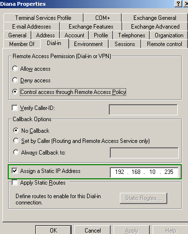
Figure30: Active Directory - Diana Properties: Dial-In - Assign A Static IP
When I will connect with the user Diana, I will receive for my PPP adapter the 192.168.10.235 IP address, see Figure31.
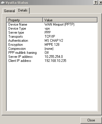
Figure31: Vyatta VPN Connection Status
I can notice with Wireshark that the IAS server assigned the desired IP address to the Diana user, see Figure32.
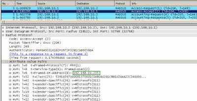
Figure32: Wireshark Capture: RADIUS messages - Static IP Address Assigned
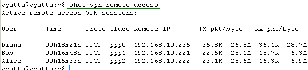
If I connect with other users, say Bob and Alice, their PPP adapters will receive IP addresses from the pool entered on Vyatta (but as said above, starting from 192.168.10.221), see Figure33.
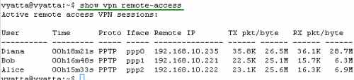
Figure33: show vpn remote-access
8. Support for Multiple PPTP Clients Located Behind the Same NAT Device at a Time
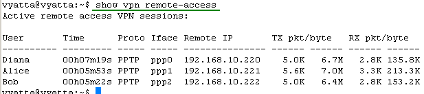
Vyatta OFR VC4's PPTP VPN Server supports this scenario, when multiple PPTP VPN clients are located behind the same NAT at a time, see Figure34 , showing three VPN clients located behind the same NAT device at the same time.
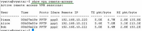
Figure34: show vpn remote-access
However the NAT device must "allow" this to happen. The NAT device uses a PPTP NAT editor, and some NAT devices have problems tracking the GRE connection and the Call ID for PPTP, thus they can merely allow only one PPTP client at a time connected to the same VPN server.
If your NAT device falls into this category, you can replace it with a Vyatta OFR machine, which does not have such problems.
9. Quick Firewall Configuration: Intro
Let's attempt to quickly configure some firewall rules on Vyatta.
Vyatta uses firewall instances per interface to filter traffic. On an interface we can have "Local", "In" and "Out" firewall instances. Figure35 provides a quick explanation of these instances.
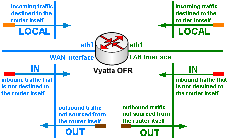
Figure35: Vyatta: Interface Firewall Instances
So we need to know the traffic not destined to the router itself that enters or exits an interface, and also the incoming traffic that is destined to the router. Note that as writing this, you cannot filter from the CLI the outgoing traffic sourced from the router itself.
Also we must know which packets are from established connections and which are used to initiate connections. Applying properly the "State" parameter within our firewall rules we greatly enhance security, enabling Vyatta to perform stateful packet filtering. Without the "State" parameter we have a basic packet filtering device (which in our days cannot be trully called a firewall). If you want to read more about Linux and stateful packet filtering you may refer to this article. And if you want to find out more about the difference between basic packet filtering and stateful packet filtering, you can read NIST Special Publication 800-41 - Guidelines on Firewalls and Firewall Policy sections 2.2. Packet Filter Firewalls and 2.3. Stateful Inspection Firewalls. It might be an old doc, but it's quite educative.
Let's imagine we have the scenario when a RADIUS server (192.168.10.2, Active Directory integrated) is used for authentication, and Diana is a special VPN user, that only needs limited access to one server (192.168.10.2) located on the internal network in order to use her HTTP application. The normal VPN clients have full access to this internal server.
Split-tunneling is disabled, so VPN clients will have web access (HTTP and HTTPS) through Vyatta.
Also internal hosts need web access (HTTP and HTTPS).
The internal server 192.168.10.2 acts as the local DNS server which uses as forwarder the external 192.168.22.1 DNS server.
This server 192.168.10.2 is actually the domain controller. Since I am in my lab, I'm not concern with security issues, so this will be just a demonstration to show how firewall rules are working.
10. Quick Firewall Configuration: Local Firewall Instance on eth1
First we will create a "Local" firewall instance named "intlocal" for the eth1 interface. This will filter packets from the internal network entering eth1 destined to the router itself. This firewall instance does not filter packets from the VPN clients destined to the router (destination IP address 192.168.10.1, so you can use a SSH client to manage your Vyatta over the VPN tunnel without adding a firewall rule within this firewall instance, actually you do not have to add a firewall rule for that in any of the firewall instances from bellow):
- I want to allow the router to be managed using SSH from a couple of internal hosts, rule 10.
- We are using a RADIUS server for user authentication located behind Vyatta, so we need to permit the RADIUS reply messages, rules 15 and 20 (for the IAS server). These packets are from established connections (connections initiated by Vyatta). Note that UDP is a connectionless transport protocol, so it does not have a state like TCP.
- In rule 25 I've allowed the DNS query responses (UDP port 53) from the local DNS to the router (the router use it as its name server). Again, these packets are from established connections (connections initiated by Vyatta).
- I want to be able to quickly test connectivity from the router to internal hosts (using the ping command), so in rule 30 I've allowed the ICMP echo-reply messages for established connections (for example connections for which the router has sent the ICMP echo-request message and is waiting the echo-reply message). Note that ICMP is also a connectionless protocol.
set firewall broadcast-ping disable
set firewall log-martians enable
set firewall receive-redirects disable
set firewall send-redirects disable
set firewall syn-cookies enable
set firewall ip-src-route disable
set firewall name eth1local rule 10 action accept
set firewall name eth1local rule 10 protocol tcp
set firewall name eth1local rule 10 source address 192.168.10.2-192.168.10.10
set firewall name eth1local rule 10 destination port 22
set firewall name eth1local rule 10 destination address 192.168.10.1
set firewall name eth1local rule 10 state new enable
set firewall name eth1local rule 10 state established enable
set firewall name eth1local rule 10 state related enable
set firewall name eth1local rule 10 state invalid disable
set firewall name eth1local rule 15 action accept
set firewall name eth1local rule 15 protocol udp
set firewall name eth1local rule 15 source address 192.168.10.2
set firewall name eth1local rule 15 source port 1812
set firewall name eth1local rule 15 destination address 192.168.10.1
set firewall name eth1local rule 15 state established enable
set firewall name eth1local rule 15 state related enable
set firewall name eth1local rule 15 state invalid disable
set firewall name eth1local rule 20 action accept
set firewall name eth1local rule 20 protocol udp
set firewall name eth1local rule 20 source address 192.168.10.2
set firewall name eth1local rule 20 source port 1813
set firewall name eth1local rule 20 destination address 192.168.10.1
set firewall name eth1local rule 20 state established enable
set firewall name eth1local rule 20 state related enable
set firewall name eth1local rule 20 state invalid disable
set firewall name eth1local rule 25 action accept
set firewall name eth1local rule 25 protocol udp
set firewall name eth1local rule 25 source address 192.168.10.2
set firewall name eth1local rule 25 source port 53
set firewall name eth1local rule 25 destination address 192.168.10.1
set firewall name eth1local rule 25 state established enable
set firewall name eth1local rule 25 state related enable
set firewall name eth1local rule 25 state invalid disable
set firewall name eth1local rule 30 action accept
set firewall name eth1local rule 30 protocol icmp
set firewall name eth1local rule 30 source address 192.168.10.0/24
set firewall name eth1local rule 30 destination address 192.168.10.1
set firewall name eth1local rule 30 icmp type 0
set firewall name eth1local rule 30 icmp code 0
set firewall name eth1local rule 30 state established enable
set firewall name eth1local rule 30 state related enable
set firewall name eth1local rule 30 state invalid disable
set interfaces ethernet eth1 firewall local name eth1local
commit
As can be seen, the firewall instance "Local" named "eth1local" was configured on the eth1 interface.
11. Quick Firewall Configuration: Local Firewall Instance on eth0
And we will also create a "Local" firewall instance named "extlocal" for the eth0 interface. This will filter packets from the external network entering eth0 destined to the router itself:
- Vyatta will terminate PPTP connections, PPTP uses TCP port 1723 and the GRE protocol, rules 10 and 15.
- NTP is used by the router, rule 20 allows the required communications (only established communications, because the router queries the NTP server, thus the router initiates the connections).
- I want to be able to quickly test connectivity from the router to external hosts (using the ping command), so in rule 25 I've allowed the ICMP echo-reply messages for established connections (for example connections for which the router has sent the ICMP echo-request message and is waiting the echo-reply message).
- SSH will be used to manage the router remotely, rule 30. Note that now since VPN remote access is available, the router can be managed over the VPN tunnel using a SSH client, so you may disable this rule. I highly recommend you to do so.
set firewall name eth0local rule 10 action accept
set firewall name eth0local rule 10 protocol tcp
set firewall name eth0local rule 10 destination port 1723
set firewall name eth0local rule 10 destination address 192.168.30.2
set firewall name eth0local rule 10 state new enable
set firewall name eth0local rule 10 state established enable
set firewall name eth0local rule 10 state related enable
set firewall name eth0local rule 10 state invalid disable
set firewall name eth0local rule 15 action accept
set firewall name eth0local rule 15 protocol gre
set firewall name eth0local rule 15 destination address 192.168.30.2
set firewall name eth0local rule 15 state new enable
set firewall name eth0local rule 15 state established enable
set firewall name eth0local rule 15 state related enable
set firewall name eth0local rule 15 state invalid disable
set firewall name eth0local rule 20 action accept
set firewall name eth0local rule 20 protocol udp
set firewall name eth0local rule 20 source address 69.59.150.135
set firewall name eth0local rule 20 source port 123
set firewall name eth0local rule 20 destination address 192.168.30.2
set firewall name eth0local rule 20 state established enable
set firewall name eth0local rule 20 state related enable
set firewall name eth0local rule 20 state invalid disable
set firewall name eth0local rule 25 action accept
set firewall name eth0local rule 25 protocol icmp
set firewall name eth0local rule 25 destination address 192.168.30.2
set firewall name eth0local rule 25 icmp type 0
set firewall name eth0local rule 25 icmp code 0
set firewall name eth0local rule 25 state established enable
set firewall name eth0local rule 25 state related enable
set firewall name eth0local rule 25 state invalid disable
set firewall name eth0local rule 30 action accept
set firewall name eth0local rule 30 protocol tcp
set firewall name eth0local rule 30 destination port 22
set firewall name eth0local rule 30 destination address 192.168.30.2
set firewall name eth0local rule 30 state new enable
set firewall name eth0local rule 30 state established enable
set firewall name eth0local rule 30 state related enable
set firewall name eth0local rule 30 state invalid disable
set interfaces ethernet eth0 firewall local name eth0local
commit
As can be seen, the firewall instance "LOCAL" named "extlocal" was configured on the eth0 interface.
12. Quick Firewall Configuration: In Firewall Instance on eth1
Next we will start creating an "IN" firewall instance for the internal interface of Vyatta, eth1.
This firewall instance will be named "eth1in".
This will filter the packets from the internal network entering the eth1 interface that are not destined to the router itself.
So we need to know what packets that are not destined to the router enter this interface:
- HTTP (TCP port 80) and HTTPS (TCP port 443) connections used for web browsing by internal users, rule 10. They will establish new connections, thus we need to specify the required "State" parameters.
- The local DNS server which uses as forwarder the external DNS server 192.168.22.1, so I will allow the required communications, rule 15 (UDP port 53)
- Packets destined to the VPN clients from the internal server 192.168.10.2 will enter this interface. These packets are from established connections (the VPN clients will initiate the connections), so I will permit only established connections from the local server (reply packets) to the VPN clients.
- In rule 20 I've allowed all the protocols for normal VPN clients.
- In rule 30 (Oops!, I've jumped from 20 to 30) I've allowed only HTTP (TCP port 80) established traffic for Diana.
- In rule 35 I've allowed the DNS query responses (UDP port 53) from the local DNS to Diana. Diana will use this DNS server to resolve DNS names.
Of course these rules do not prevent VPN clients to send packets to internal computers, they only block unwanted replies from these computers, allowing only the reply messages that we specify. For blocking VPN clients to send packets to certain internal computers we will use an "Out" firewall instance on interface eth1.
Note that Bug 2122 not been solved in Vyatta VC4, so I might be able to pass, for example, a lonely ACK segment through Vyatta, even if there is no TCP connection established.
set firewall name eth1in rule 10 action accept
set firewall name eth1in rule 10 protocol tcp
set firewall name eth1in rule 10 source address 192.168.10.2-192.168.10.210
set firewall name eth1in rule 10 destination port 80,443
set firewall name eth1in rule 10 destination address !192.168.10.220-192.168.10.240
set firewall name eth1in rule 10 state new enable
set firewall name eth1in rule 10 state established enable
set firewall name eth1in rule 10 state related enable
set firewall name eth1in rule 10 state invalid disable
set firewall name eth1in rule 15 action accept
set firewall name eth1in rule 15 protocol udp
set firewall name eth1in rule 15 source address 192.168.10.2
set firewall name eth1in rule 15 destination port 53
set firewall name eth1in rule 15 destination address 192.168.22.1
set firewall name eth1in rule 15 state new enable
set firewall name eth1in rule 15 state established enable
set firewall name eth1in rule 15 state related enable
set firewall name eth1in rule 15 state invalid disable
set firewall name eth1in rule 20 action accept
set firewall name eth1in rule 20 protocol all
set firewall name eth1in rule 20 source address 192.168.10.2
set firewall name eth1in rule 20 destination address 192.168.10.220-192.168.10.230
set firewall name eth1in rule 20 state established enable
set firewall name eth1in rule 20 state related enable
set firewall name eth1in rule 20 state invalid disable
set firewall name eth1in rule 30 action accept
set firewall name eth1in rule 30 protocol tcp
set firewall name eth1in rule 30 source address 192.168.10.2
set firewall name eth1in rule 30 destination address 192.168.10.235
set firewall name eth1in rule 30 source port 80
set firewall name eth1in rule 30 state established enable
set firewall name eth1in rule 30 state related enable
set firewall name eth1in rule 30 state invalid disable
set firewall name eth1in rule 35 action accept
set firewall name eth1in rule 35 protocol udp
set firewall name eth1in rule 35 source address 192.168.10.2
set firewall name eth1in rule 35 destination address 192.168.10.235
set firewall name eth1in rule 35 source port 53
set firewall name eth1in rule 35 state established enable
set firewall name eth1in rule 35 state related enable
set firewall name eth1in rule 35 state invalid disable
set interfaces ethernet eth1 firewall in name eth1in
commit
As can be seen the firewall instance "In" named "eth1in" was configured on the eth1 interface.
13. Quick Firewall Configuration: In Firewall Instance on eth0
Now we move to the external interface of Vyatta, eth0 and we will create an "In" firewall instance for the external interface of Vyatta, eth0.
This firewall instance will be named "eth0in".
This will filter the packets from the external network entering the eth0 interface that are not destined to the router itself (it will also filter the packets entering the eth0 interface that are destined to the VPN clients in case split-tunneling is disabled):
- packets from connections already established by the internal hosts, HTTP and HTTPS connections (web access), rule 10.
- packets from connections already established by the internal DNS server, DNS connections, rule 15.
- packets from connections already established by the normal VPN clients, HTTP and HTTPS connections (web access), rule 20.
- packets from connections already established by the VPN client Diana, HTTP and HTTPS connections (web access), rule 25.
set firewall name eth0in rule 10 action accept
set firewall name eth0in rule 10 protocol tcp
set firewall name eth0in rule 10 source port 80,443
set firewall name eth0in rule 10 destination address 192.168.10.2-192.168.10.210
set firewall name eth0in rule 10 state established enable
set firewall name eth0in rule 10 state related enable
set firewall name eth0in rule 10 state invalid disable
set firewall name eth0in rule 15 action accept
set firewall name eth0in rule 15 protocol udp
set firewall name eth0in rule 15 source port 53
set firewall name eth0in rule 15 destination address 192.168.10.2
set firewall name eth0in rule 15 source address 192.168.22.1
set firewall name eth0in rule 15 state established enable
set firewall name eth0in rule 15 state related enable
set firewall name eth0in rule 15 state invalid disable
set firewall name eth0in rule 20 action accept
set firewall name eth0in rule 20 protocol tcp
set firewall name eth0in rule 20 source port 80,443
set firewall name eth0in rule 20 destination address 192.168.10.220-192.168.10.230
set firewall name eth0in rule 20 state established enable
set firewall name eth0in rule 20 state related enable
set firewall name eth0in rule 20 state invalid disable
set firewall name eth0in rule 25 action accept
set firewall name eth0in rule 25 protocol tcp
set firewall name eth0in rule 25 source port 80,443
set firewall name eth0in rule 25 destination address 192.168.10.235
set firewall name eth0in rule 25 state established enable
set firewall name eth0in rule 25 state related enable
set firewall name eth0in rule 25 state invalid disable
set interfaces ethernet eth0 firewall in name eth0in
commit
Note that the firewall instance "In" named "eth0in" was configured on the eth0 interface.
14. Quick Firewall Configuration: Out Firewall Instance on eth1
If we want to allow Diana or any VPN user to send packets to a certain destination from the internal network, we need to configure an "Out" firewall instance on eth1.
This will filter packets exiting interface eth1 (as said before it will not apply to packets sourced from the router itself exiting the interface, as currently you cannot filter packets from the router itself exiting an interface from the CLI):
- the normal VPN clients have full access to the internal server (they will initiate connections), rule 10.
- the VPN user Diana will have limited access to the internal server (she will initiate connections), rule 15.
- also since 192.168.10.2 is the DNS server, Diana will use it to resolve host names, rule 30.
- packets from connections already established by the internal hosts, HTTP and HTTPS connections (web access), rule 25.
- packets from connections already established by the internal DNS server, DNS connections, rule 30.
set firewall name eth1out rule 10 action accept
set firewall name eth1out rule 10 protocol all
set firewall name eth1out rule 10 destination address 192.168.10.2
set firewall name eth1out rule 10 source address 192.168.10.220-192.168.10.230
set firewall name eth1out rule 10 state new enable
set firewall name eth1out rule 10 state established enable
set firewall name eth1out rule 10 state related enable
set firewall name eth1out rule 10 state invalid disable
set firewall name eth1out rule 15 action accept
set firewall name eth1out rule 15 protocol tcp
set firewall name eth1out rule 15 destination address 192.168.10.2
set firewall name eth1out rule 15 source address 192.168.10.235
set firewall name eth1out rule 15 destination port 80
set firewall name eth1out rule 15 state new enable
set firewall name eth1out rule 15 state established enable
set firewall name eth1out rule 15 state related enable
set firewall name eth1out rule 15 state invalid disable
set firewall name eth1out rule 20 action accept
set firewall name eth1out rule 20 protocol udp
set firewall name eth1out rule 20 destination address 192.168.10.2
set firewall name eth1out rule 20 source address 192.168.10.235
set firewall name eth1out rule 20 destination port 53
set firewall name eth1out rule 20 state new enable
set firewall name eth1out rule 20 state established enable
set firewall name eth1out rule 20 state related enable
set firewall name eth1out rule 20 state invalid disable
set firewall name eth1out rule 25 action accept
set firewall name eth1out rule 25 protocol tcp
set firewall name eth1out rule 25 destination address 192.168.10.2-192.168.10.210
set firewall name eth1out rule 25 source address !192.168.10.220-192.168.10.240
set firewall name eth1out rule 25 source port 80,443
set firewall name eth1out rule 25 state established enable
set firewall name eth1out rule 25 state related enable
set firewall name eth1out rule 25 state invalid disable
set firewall name eth1out rule 30 action accept
set firewall name eth1out rule 30 protocol udp
set firewall name eth1out rule 30 destination address 192.168.10.2
set firewall name eth1out rule 30 source address 192.168.22.1
set firewall name eth1out rule 30 source port 53
set firewall name eth1out rule 30 state established enable
set firewall name eth1out rule 30 state related enable
set firewall name eth1out rule 30 state invalid disable
set interfaces ethernet eth1 firewall out name eth1out
commit
Note that the firewall instance "Out" named "eth1out" was configured on the eth1 interface.
15. Quick Firewall Configuration: Out Firewall Instance on eth0
If we want to allow Diana or any VPN user to send packets to Internet hosts using only certain protocols (say HTTP and HTTPS) - split tunneling is disabled -, we need to configure an "Out" firewall instance on eth0.
This will filter packets exiting interface eth0 (as said before it will not apply to packets sourced from the router itself exiting the interface, as currently you cannot filter packets from the router itself exiting an interface from the CLI):
- HTTP (TCP port 80) and HTTPS (TCP port 443) connections used for web browsing by internal users, rule 10. They will establish new connections, thus we need to specify the required "State" parameters.
- The local DNS server which uses as forwarders the external DNS server 192.168.22.1, so I will allow the required communications, rule 15 (UDP port 53).
- HTTP (TCP port 80) and HTTPS (TCP port 443) connections used for web browsing by normal VPN clients, rule 20. They will establish new connections, thus we need to specify the required "State" parameters.
- HTTP (TCP port 80) and HTTPS (TCP port 443) connections used for web browsing by the VPN user Diana, rule 25. Diana will establish new connections, thus we need to specify the required "State" parameters.
set firewall name eth0out rule 10 action accept
set firewall name eth0out rule 10 protocol tcp
set firewall name eth0out rule 10 source address 192.168.10.2-192.168.10.210
set firewall name eth0out rule 10 destination port 80,443
set firewall name eth0out rule 10 state new enable
set firewall name eth0out rule 10 state established enable
set firewall name eth0out rule 10 state related enable
set firewall name eth0out rule 10 state invalid disable
set firewall name eth0out rule 15 action accept
set firewall name eth0out rule 15 protocol udp
set firewall name eth0out rule 15 source address 192.168.10.2
set firewall name eth0out rule 15 destination address 192.168.22.1
set firewall name eth0out rule 15 destination port 53
set firewall name eth0out rule 15 state new enable
set firewall name eth0out rule 15 state established enable
set firewall name eth0out rule 15 state related enable
set firewall name eth0out rule 15 state invalid disable
set firewall name eth0out rule 20 action accept
set firewall name eth0out rule 20 protocol tcp
set firewall name eth0out rule 20 source address 192.168.10.220-192.168.10.230
set firewall name eth0out rule 20 destination port 80,443
set firewall name eth0out rule 20 state new enable
set firewall name eth0out rule 20 state established enable
set firewall name eth0out rule 20 state related enable
set firewall name eth0out rule 20 state invalid disable
set firewall name eth0out rule 25 action accept
set firewall name eth0out rule 25 protocol tcp
set firewall name eth0out rule 25 source address 192.168.10.235
set firewall name eth0out rule 25 destination port 80,443
set firewall name eth0out rule 25 state new enable
set firewall name eth0out rule 25 state established enable
set firewall name eth0out rule 25 state related enable
set firewall name eth0out rule 25 state invalid disable
set interfaces ethernet eth0 firewall out name eth0out
commit
Note that the firewall instance "Out" named "eth0out" was configured on the eth0 interface.
16. Quick Firewall Configuration: Testing
Now we can proceed and test connectivity, if we are not blocked by our firewall rules or if our firewall rules allow unpermitted traffic to pass through.
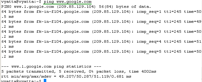
Some quick connectivity tests from the router, see Figure36 and Figure37.
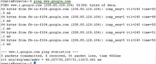
Figure36: Ping an External Host from the Router
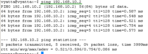
Figure37: Ping a Local Host from the Router
Let's view the statistics information for our firewall instances, see Figure38, Figure39, Figure40, Figure41, Figure42 and Figure43. They will tell us if our firewall rules filtered or not the traffic.
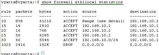
Figure38: show firewall eth1local statistics
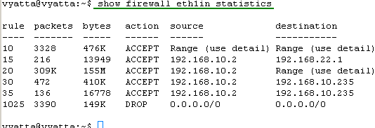
Figure39: show firewall eth1in statistics
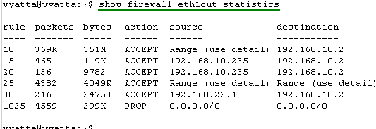
Figure40: show firewall eth1out statistics
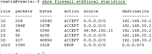
Figure41: show firewall eth0local statistics
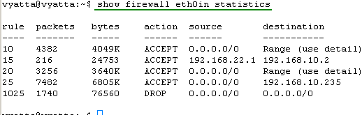
Figure42: show firewall eth0in statistics
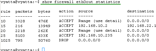
Figure43: show firewall eth0out statistics
So it looks that all of our firewall rules filter the traffic.
Let's do a quick nmap scan on the external interface of Vyatta, see Figure44.
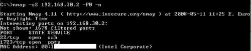
Figure44: Quick Nmap Scan
As expected, nmap found two open ports on our external interface, SSH and PPTP.
The configuration lines:
- Remote Access VPN: PPTP Local Authentication
- Remote Access VPN: PPTP RADIUS Authentication
- Remote Access VPN: PPTP RADIUS Authentication + Firewall Rules
In Part 2 we will configure L2TP/IPsec remote access with pre-shared keys as IKE authentication.
|