|
31.08.2007
Creating a site-to-site VPN Hub and Spoke architecture with ISA 2006 Firewall Standard Edition
- 1. Overview
- 2. Configure ISAA - The connection to ISAB
- 3. Configure ISAA - The connection to ISAC
- 4. Add the Users Branch and Branch2 on ISAA
- 5. Allow the Traffic Between the Branch Offices through ISAA
- 6. Configure ISAB - The connection to ISAA, and ISAC through ISAA
- 7. Add the User Main on ISAB
- 8. Configure ISAC - The connection to ISAA, and ISAB through ISAA
- 9. Add the User Main1 on ISAC
- 10. Test the s2s Connections
1. Overview
Let's assume that you have three different locations, LocationA, LocationB and LocationC. LocationA, LocationB and LocationC are protected using ISA 2006 Firewalls Standard Edition. Each location has one Internet connection.
You would like to connect all the locations togheter.
So you think on using site-to-site VPN connections. You have opted for L2TP/IPsec connections.
There is a site-to-site VPN connection between LocationA and LocationB.
There is a site-to-site VPN connection between LocationA and LocationC.
ISAA at LocationA(HQ) is acting like a hub. Communications from LocationB to LocationCand vice-versa must pass through ISAA. LocationA and LocationB are branch offices.
Bellow is the network diagram.
SiteA IP address range: 192.168.10.0/24
SiteB IP address range: 192.168.40.0/24
SiteC IP address range: 192.168.50.0/24
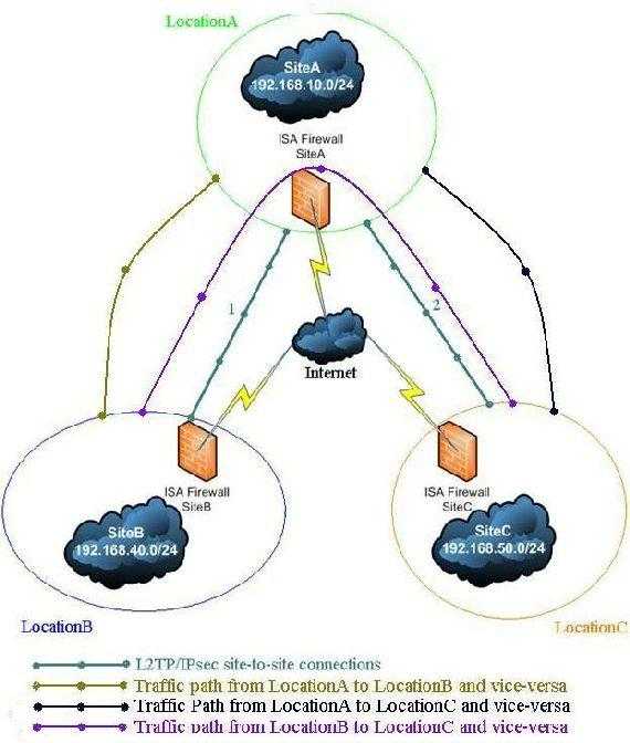
Figure1: The network diagram
2. Configure ISAA - The connection to ISAB
First we must set up ISAA(a domain member).
We need to create two site-to-site VPN connections. One to ISAB and one to ISAC.
First the connection to ISAB.
ISA can play the role of the Calling Gateway or the Answering Gateway. Suppose that a client from SiteB wants to connect to a computer from SiteA. Since the tunnel is not up yet, whenISAB at the SiteB will receive the client request will try to initiate the connection. In this wayISAB is acting as the Calling Gateway. Obviuosly ISAA(domain member) will be the Answering Gateway. Remember that L2TP/IPsec requires two level of authentication: machine(through IKE) and user(PPP authentication). So we need to configure ISAB with a user name and password that are available at the ISAA location, user which has “Dial-in” permissions set to allowed. Even more, the user name must match the remote site name fromISAA.
Using the site-to-site wizard we are going to create on ISAA the connection to ISAB, We'll name it Branch. 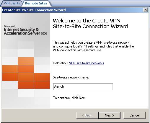
Figure2: Site-to-site wizard on ISAA adding the connection to ISAB
Choose L2TP/IPsec: 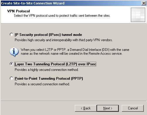
Figure3: Choosing L2TP/IPsec
We receive the user warning that I have told you about: 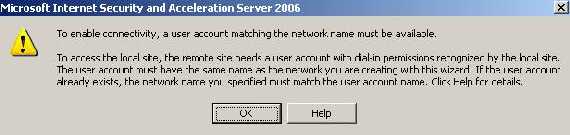
Figure4: User account warning
Enter the remote site address(it can be an IP address or a FQDN): 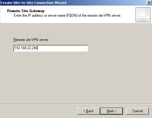
Figure5: The Remote site VPN server
You can configure ISAA to act as the Calling Gateway for this connection(at least one side must be configured to do so). We’ll name the user Main. If you want that only ISAB to initiate the connection to ISAA uncheck the checkbox: 
Figure6: Allow ISAA to act as the Calling Gateway
Next we need to specify the outgoing authentication method for IKE when ISAA is acting as the Calling Gateway. Make sure you use certificates and not pre-shared key in a production environment. Right now I’m going to use a pre-shared key. 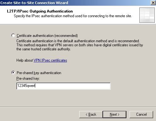
Figure7: IKE authentication when ISAA acts as the Calling Gateway
If you did not enable “VPN Client Access” and there specified for example a pre-shared key you will be prompted by ISA to define an authentication method for incoming connections. 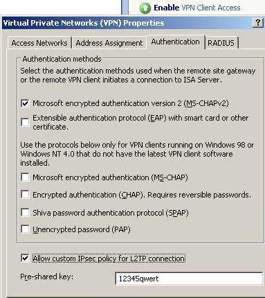
Figure8: Enable VPN Client Access
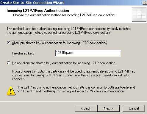
Figure9: Incoming connections Authentication method
If ISAA is the Answering Gateway and you are using pre-shared keys make sure you add a pre-shared key.
I know is weird, but actually the Calling Gateway is "acting" like a "VPN client" and therefore if you use pre-shared keys on the Answering Gateway for VPN clients too, then everybody(Calling Gateways and VPN clients) will use the same pre-shared key. Keep in mind that there are separate System Policies enabled for you by ISA(when you click “EnableVPN Client Access” or define a site-to-site VPN) for VPN clients and site-to-site connections so you do not need to create any access rules or whatever. 
Figure10: System Policy VPN client access enabled(PPTP and L2TP/IPsec)
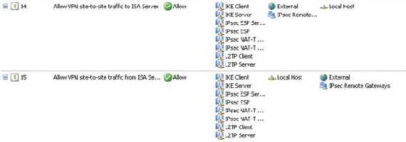
Figure11: System Policy VPN site-to-site enabled
Add the remote site IP address range: 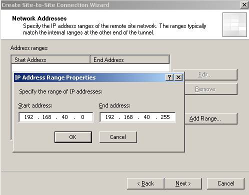
Figure12: Remote site IP address range
Next create a network rule between the new remote site and your Internal Network(a route relationship): 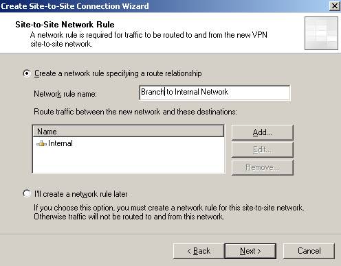
Figure13: The network relationship
And the access rules for allowing communications between Branch and Internal and vice-versa. Right now I have defined an allow all rule. 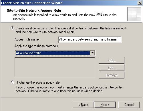
Figure14: The access rule
And then click “Finish”.
So by now you should have the System Policies enabled, the access rules and the network relationship defined: 
Figure15: Access rule between Branch and Internal and vice-versa

Figure16: Network rule between Branch and Internal
Now head onto RRAS and make sure you uncheck the “Register this connection’s addresses in DNS” on the “Branch” interface: 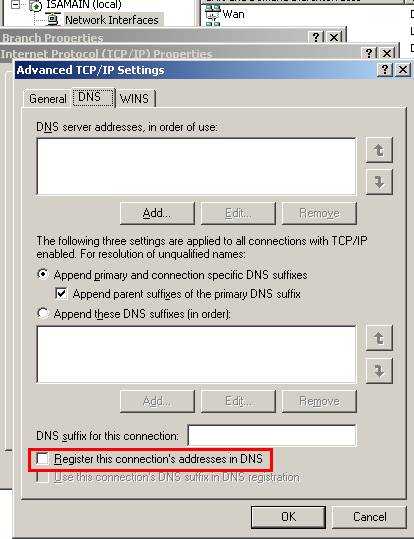
Figure17: Uncheck the “Register this connection’s addresses in DNS”
3. Configure ISAA - The connection to ISAC
Now we will repeat the above steps for creating the site-to-site connection to ISAC.
We’ll name it Branch2: 
Figure18: The site-to-site connection from ISAA to ISAC
Choose again L2TP/IPsec and enter the server address: 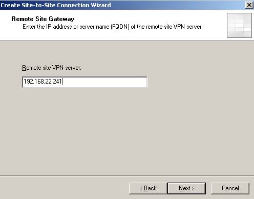
Figure19: The Remote site VPN server
For avoiding confusion let’s call the user Main1. 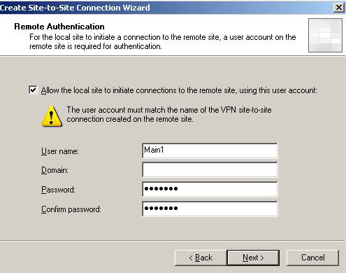
Figure20: User name when ISAA is acting as the Calling Gateway for ISAC
Configure the outgoing authentication method for IKE(I have used the pre-shared key12345qwert). Define the remote site range: 192.168.50.0/24, the access rules and network rules. 
Figure21: Branch2 remote site on ISAA
Don’t forget about the RRAS setting and uncheck the “Register this connection’s addresses in DNS” for “Branch2” interface.
4. Add the Users Branch and Branch2 on ISAA
And we need to define two users Branch(matching ISAB remote site name from ISAA) and Branch2(matching ISAC remote site name from ISAA) in order to enable ISAA to act as the Answering Gateway for the two site-to-site connections. As said before they will be used byISAB and ISAC. Since ISAA is a domain member we are going to define the users in Active Directory. 
Figure22: The users
Don’t forget to set their “Dial-in” permission(you can use “Control access through Remote Access Policy” but let’s keep it simple right now): 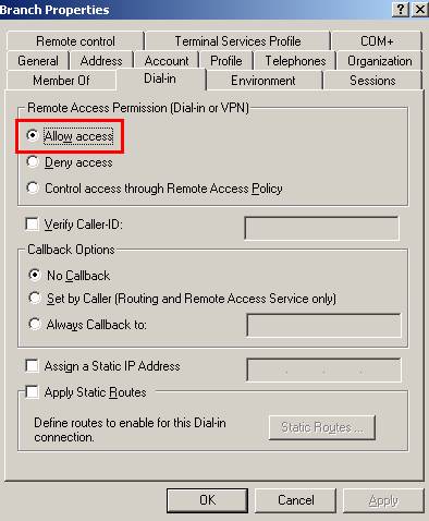
Figure23: Branch user “Dial-in” permission
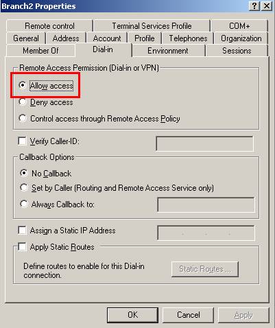
Figure24: Branch2 user “Dial-in” permission
5. Allow the Traffic Between the Branch Offices through ISAA
Now let's visualize the site-to-site summary for Branch:
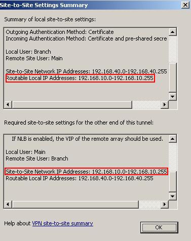
Figure25: Branch site-to-site summary
As we can see at the local side only 192.168.10.0/24 is routable. This means that the remote side can only access resources located on the Internal Network(remember that we have define a route network relationship). Also ISAA "expects" that ISAB remote site range to be 192.168.10.0/24 and between this remote site and the local ISAB network 192.168.40.0/24 to exist a network relationship.
The Branch2 site-to-site summary:
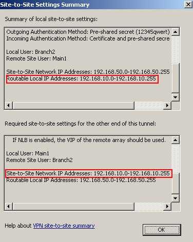
Figure25: Branch site-to-site summary
Again at the local side only 192.168.10.0/24 is routable. This means that the remote side can only access resources located on the Internal Network(remember that we have define a route network relationship). Also ISAA "expects" that ISAC remote site range to be 192.168.10.0/24 and between this remote site and the local ISAC network 192.168.50.0/24 to exist a network relationship.
What we are going to do is to create on ISAA a route network relationship between Branch and Branch2 and create an access rule allowing access between the two networks.

Figure26: Network rule between Branch and Branch2

Figure27: Access rule between Branch and Branch2
And let's look one more time at the Branch site-to-site summary on ISAA:
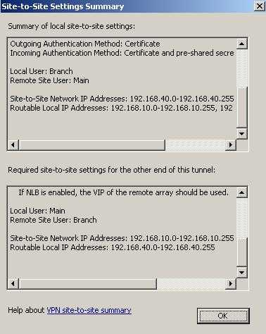
Figure28: New Branch site-to-site summary
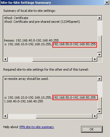
Figure29: New Branch site-to-site summary, new routable addresses
As we can see at the ISAA side, now 192.168.50.0/24 is also a local routable network. ISAA"expects" that ISAB remote site range to be 192.168.10.0/24 plus 192.168.50.0/24 and between this remote site and the local ISAB network 192.168.40.0/24 to exist a network relationship.
And the Branch2 site-to-site summary:
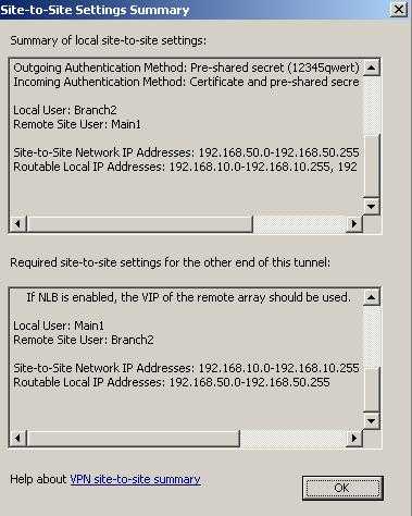
Figure30: New Branch2 site-to-site summary
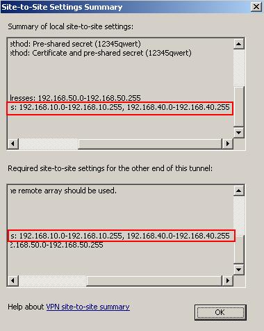
Figure31: New Branch2 site-to-site summary, new routable addresses
As we can see at the ISAA side, now 192.168.40.0/24 is also a local routable network. ISAA"expects" that ISAC remote site range to be 192.168.10.0/24 plus 192.168.40.0/24 and between this remote site and the local ISAC network 192.168.50.0/24 to exist a network relationship.
So since we created a network rule between Branch and Branch2 now ISA will route traffic between the two networks(route relationship). And we have the access rules in place in order that communications to be allowed.
And we are done with ISAA.
6. Configure ISAB - The connection to ISAA, and ISAC through ISAA
Moving to ISAB now.
Define the site-to-site connection with ISAA, which also allows traffic to ISAC through ISAA.
We'll name it Main(the user name we defined on ISAA in the wizard): 
Figure32: Main remote site on ISAB
Choose L2TP/IPsec. Enter ISAA address: 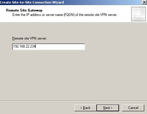
Figure33: The Remote site VPN server
The user name will be Branch since this is how on ISAA is named the remote site. 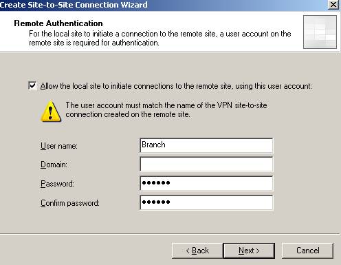
Figure34: The user on ISAB required for ISAB to act as the Calling Gateway Next, if ISAA is configured to accept incoming connections using pre-shared keys for IKE authentication make sure you fill the correct pre-shared key on ISAB(outgoing authentication): 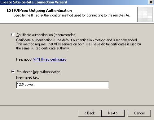
Figure35: Outgoing Authentication on ISAB
And probably you will be prompted for authentication for incoming connections(use the pre-shared key with which ISAA is configured to initialize connections):

Figure36: Incoming Authentication
OK. I will use everywhere the same pre-shared key. Remember if ISAA acts as the Answering Gateway and ISAB and ISAC as the Calling Gateways, ISAB and ISAC will use the same pre-shared key for outgoing authentication.
The IP address range is 192.168.10.0/24 and 192.168.50.0.
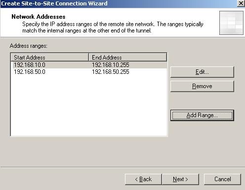
Figure37: Remote site Main on ISAB
Create the network rule and access rules. 
Figure38: Access rules

Figure39: Network rule
Don’t forget about the RRAS setting and uncheck the “Register this connection’s addresses in DNS” for the “Main” interface.
7. Add the User Main on ISAB
Since ISAB is not yet joined to the domain(it will be after the site-to-site connection is up) we will define a local user called Main with his “Dial-in” permissions set to allowed. 
Figure40: ISAB local user
And ISAB is good to go.
8. Configure ISAC - The connection to ISAA, and ISAB through ISAA
Moving to ISAC.
The site-to-site connection to ISAA, which also allows traffic to ISAB through ISAA. We’ll name it Main1 as the user define on ISAA in the wizard. 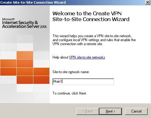
Figure41: The site-to-site VPN connection from ISAC to ISAA
Select the L2TP/IPsec connection. The remote server address is 192.168.22.234.
The user name is Branch2, like the remote site defined on ISAA. 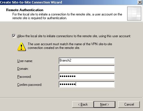
Figure39: The user used by ISAC to act as the Calling Gateway against ISAA
The outgoing authentication. 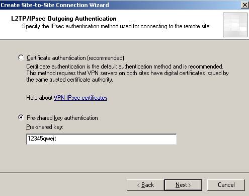
Figure40: The outgoing authentication
If you are prompted for incoming authentication you must match it with one configured on ISAA(for outgoing): 
Figure41: The incoming authentication
The IP address range is 192.168.10.0/24 and 192.168.40.0/24
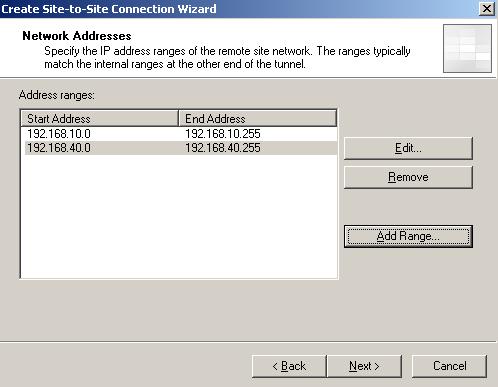
Figure42: Main1 remote site range
Configure the network rule(route relationship) and the access rules.
Don’t forget about the RRAS setting and uncheck the “Register this connection’s addresses in DNS” for “Main1” interface.
9. Add the User Main1 on ISAC
And let’s add a local user(ISAC is not a domain member yet), Main1 with the “Dial-in” permission set to allowed. 
Figure43: ISAC local user
And ISAC is good to go.
10. Test the s2s Connections
Let's assume that no tunnel is yet up between ISAB and ISAA. A user from 192.68.40.2(behind ISAB) will try to contact a computer behind ISAA(192.168.10.2).
So the tunnel must come up. A ping command:
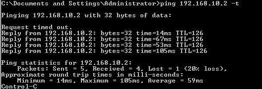
Figure44:Bringing the tunnel up between ISAB and ISAA
Let's assume that the same user wants to contact a computer(192.168.50.10) situated behindISAC.
So traffic will go through ISAA to ISAC. Since right now the tunnel is not up yet between ISAAand ISAB, ISAA will act as the Calling Gateway to ISAC.
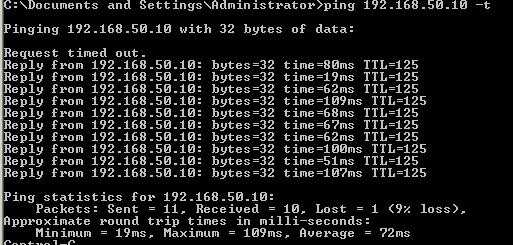
Figure44:Bringing the tunnel up between ISAA and ISAC
And it worked.
A quick test from a computer behind ISAC, 192.168.50.10 to see if can access resources located behind ISAA and ISAB.
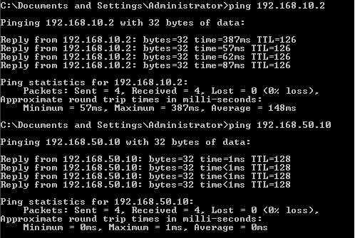
Figure45: Ping test behind ISAC
A quick test from a computer behind ISAA, 192.168.10.2 to see if can access resources located behind ISAB and ISAC.
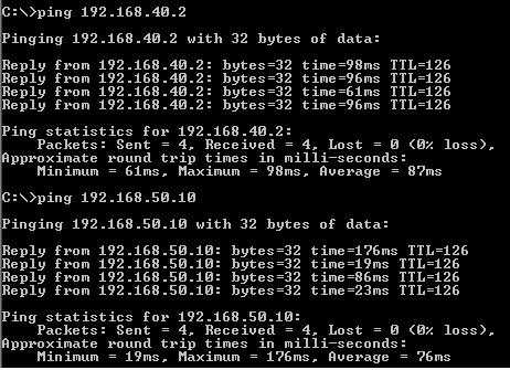
Figure46: Ping test behind ISAA
And things seem to work.
You can now proceed and join ISAB and ISAC to the domain if you want. Actually if you could, it was better to prepare ISAB and ISAC on LocationA. Install additional domain controllers on LocationB and LocationC and so on.
Remember to use certificates for IKE authentication. Use pre-shared keys only for testing. You can go and configure EAP-TLS for user authentication instead of ms-chapv2.
That's it!
If you want a related article to ISA Enterprise Edition please refer to the below article:
http://www.microsoft.com/technet/isa/2004/plan/vpn_deployment_ee.mspx
|